
Before reading this documentation, get a rough overview of HP4's features.
This documentation might still have gaping holes here and there. Please help improving it by following the contribution guide.
If you're building a v4, say hi and connect with other builders in the discord channel.

In the repo, there's an Openscad file called
layout.scad.
Open that file with Openscad.
It shows all the parts, including where and how they're supposed to be mounted.
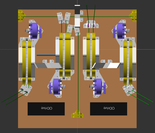
layout.scad file with Openscad.
Rotate the view (inside Openscad) by clicking and dragging with your mouse.
Zoom by scrolling your scroll wheel.
If you want help with positioning parts on the ceiling unit in the most compact and standard way possible, 2d print out the layout_a4.pdf and use it as a template.
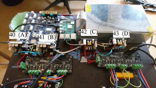
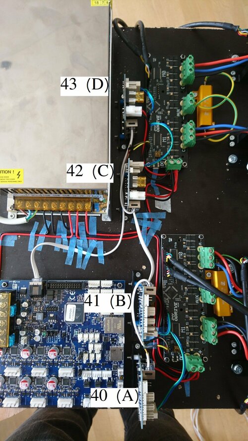
As for the circuit boards and the power supply, place them out in a configuration similar to this:
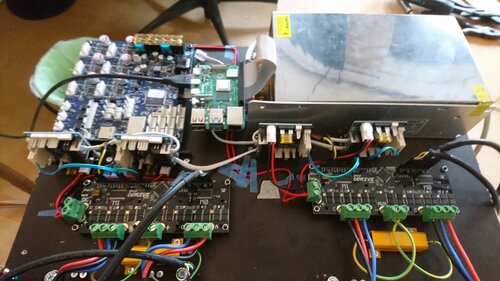
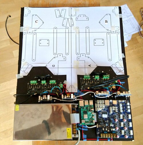
Hot tips for circuit board placement:
It can be tricky to get the nuts into the right places on the motor brackets. It's recommended to use a nylock nut to secure the encoder in place.
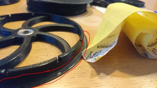
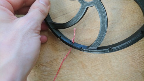
The line is easy to fray, and 3d-printing sometimes leaves sharp and pointy edges. It's therefore recommended to sand down the inside of the spool disc, like this:
First of all, press a bearing into each spool, and rotate each spool separately on your 8mm spool core rod.
If a spool has warped, it's useless. Otherwise, if it rotates straight enough, move on to the next step: snapping on the GT2 spool gear.
The spool and the GT2 spool gear snap together with a very tight tolerance. When you press fit them together, you can usually hear a sharp "tick" each time the two parts' layer lines mesh in place.
A common problem is that the GT2 spool gear is so tight, that it warps the whole spool, and/or doesn't mesh with the same layer line all around the spool. Check this with a similar test as before.
If you see wobbly rotation like in the video above, you must take off your GT2 gear from your spool and file/sand down sharp edges and layer lines.
Take off any squeezed out edge from top/bottom layers on both GT2 spool gear, and on the spool itself. In some cases, I also widen the pocket on the top of the spool, where the inner tooth of the GT2 spool gear sinks into.
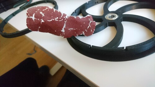
Sometimes it helps to separate the spool's parts, rotate them relative to each other, and re-assemble. A tiny warp in one spool part might cancel out an equal tiny warp in another spool part, or amplify it, depending on how the parts are rotated before press fitting them together.
Getting all spools to rotate straight will help your machine become more silent, because it won't rub into the inner walls of the spool cover. It will also make your machine more safe, because it will help the spool cover casettes fully enclose your spools so that line can't escape and get tangled into the motor.
The encoders must be mounted perfectly straight onto the motor shaft, so that the motor can rotate freely. If you hear a rubbing sound from the encoder when you rotate the motor, then you should adjust the encoder's placement.
The motor bracket tries to help you fixate the encoder perfectly. But sometimes the encoder ends up with a degree or so of rotation that the bracket won't let you adjust easily. In those cases, I adjust the rotational position of the encoder like this:
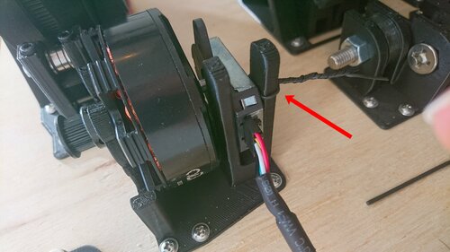
Warning: The motor wires must be connected in the exact order shown below. Otherwise torque mode would run backwards and create chaos. Also, auto-calibration wouldn't work because signs would be reversed.
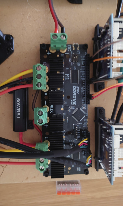
Another Warning: The step/dir inputs of the ODrive v3s are not opto-decoupled. This means we will have some signal noise in the all-important step/dir signal wires.
The amount of signal noise depends on the area of the loop described below:
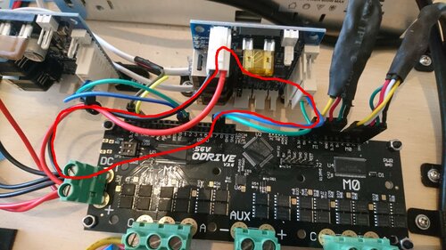
Because both the ODrive and the 1XD boards are connected to GND, there will exist ground loops like the one described above. Try to make them as small as possible in terms of area. This is best done by connecting the ODrive's GND and the 1XD's GND together, like shown in the image above.
The risk of step/dir signal noise is inherent in the ODrive v3 design. I have never had problems with this in practice but I always connect the two GNDs together just in case.
The step/dir wires themselves are connected to ODrives 7/8 and 1/2 GPIO pairs (see your ODrive config file) in on end. In the other end, they connect to the 1XD board's D0_STEP(+) and D0_DIR(+) logic pins. (See 1XD wiring diagram.)
Check 1XD's termination jumpers, that are shown in the 1XD wiring diagram. Only 1XD nr 40 (the A-motor's 1XD board, at the farthest physical end of the CAN bus) should have it's termination jumpers in place. The three other 1XD boards should not have termination jumpers.
For all other wiring see
The Duet3 has two CAN buses coming out of its RJ11 (6P4C) contact. These two CAN buses live separately, in two different pairs of wires.
The two centermost conductors in the 6P4C contact carry the main CAN bus. It transfers step/dir signals from the Duet3 to the 1XDs.
The rightmost and leftmost pins are not in use in 6P4C contacts. So we have two remaining conductors that are not used by the main CAN bus. The two remaining conductors carry the ODrives' CAN bus.
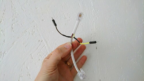
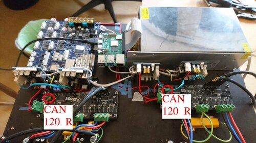
The ODrives' CAN bus also goes inside the white wire, at least on my machine. It goes from the Duet3, through board 43, branches off into one ODrive, the other branch continues through board 42, through board 41, and ends in the second ODrive (left one on the image below). The 1XD boards does not and can not read the ODrives' CAN bus. It just passes straight through the 1XD boards.
With the ODrive CAN bus wired up, make sure you set the termination resistors correctly:
Note: Most users will not have to think about versions of ReprapFirmware, or installing ReprapFirmware directly. All that is handled by the DuetPi operating system on the Raspberry Pi. Here follows some details anyways, just for your information.
There is Hangprinter v4 support in official RepRapFirmware Release 3.3 and onwards.
At the time of writing this (March 30, 2022), it's recommended to use the latest official release: Release 3.4.
In addition to ReprapFirmware's official releases, beta releases and so on, I (tobben) always publish my latest RepRapFirmware build here: link. My personal builds are only meant to be used during debugging, beta testing of new features, or in other exceptional circumstances.
The SD card shipped with the Duet3 MB6HC boards already have DuetPi on them.
Insert the SD card into your laptop. Create a new file in the boot partition called
wpa_supplicant.conf.
Fill the file with your network details, similar to this:
          update_config=1

          ctrl_interface=/var/run/wpa_supplicant


          network={

            ssid="YOUR_NETWORKS_SSID"

            psk="YOUR_NETWORKS_PASSPHRASE"

          }
Insert your SD card into your Raspberry Pi. Connect a display, a keyboard, and a mouse to your Raspberry Pi, and power it up.
Press F11 to get rid of the DuetWebControl interface.
Find the Preferences -> Raspberry Pi Configuration
in the topleft system menu.
One of the tabs there lets you enable both SSH and Camera.
You can now shut down your Rapsberry Pi. Disconnect the display, keyboard, and mouse. Connect your Raspberry Pi to the Duet3 MB6HC board with the ribbon cable that is included in the Duet3 MB6HC package.
Power up your Raspberry Pi (probably with a separate USB-C power supply) and your Duet3 MB6HC board (probably with a 24V power supply).
Ssh into your Raspberry Pi, like this
$ ssh pi@duet3.local
If you use a non-official release of ReprapFirmware (a beta, a release candidate, or a tobben-build), it's recommended to enable the unstable software repository. Most users should use not use the unstable software repository.
Whether you enabled the unstable software repository or not, you can now upgrade the software on the Raspberry Pi and the Duet3 board simultaneously, like this
$ sudo apt update && sudo apt upgrade
Congrats, your Raspberry Pi is good to go.
Type exit in your ssh window and hit enter to close the ssh connection.
If you're going to set up the computer vision system (hp-mark), there will be some more Raspberry Pi related
things to set up later.
Use a web browser and type http://duet3.local/ in the address bar.
The Duet Web Interface should show up.
Your machine will not work as a Hangprinter yet.
It needs to be configured first, with a proper confing.g file in your System Directory.
You can have a look at my example
config.g for RepRapFirmware for reference.
The config.g file includes calibration values (M669) that are tricky to get right. We'll get back to the M669 calibration values later in this manual.
Use the USB isolator between your laptop and your ODrive.
These instructions are for ODrivefirmware v0.5.5 (lastest release at time of writing, Sep 21, 2022). New boards bought after Sep 21, 2022 should come with v0.5.5 pre-flashed.
Install odrivetool v0.6.3: If you're on Ubuntu, something like this should work:
$ sudo apt install python3 python3-pip
$ sudo pip3 install odrive==0.6.3
Otherwise refer to ODrive docs on how to install odrivetool v0.6.3 here.
If your board has an old (<0.5.5) firmware version, upgrade it with
$ odrivetool dfu
If it gets stuck at "Putting device XXXXXXXXXXXX into DFU mode...", it can help to stop it with Ctrl+C and simply try again.
If it gets stuck every time, pull the power plug, flip the switch on the ODrive board from RUN to DFU, and try again. Just remember to flip it back to RUN afterwards.
To configure your AB board (connected to the A- and B-motors), do a config restore of the AB config found in the Hangprinter repo:
$ odrivetool restore-config </path/to>/hangprinter/firmware/ODrive/odrive-config-AB.json
This will set most configuration values about right. However, there are a few you need to change.
You must measure the correct value with a multimeter over your break resistor.
Open up odrivetool and set
odrv0.config.brake_resistance = your_measured_value
Also, you need to do a full calibration sequence of both axes. Copy these lines into odrivetool
one-by-one
and hit Enter in between each.
        odrv0.axis0.requested_state = AXIS_STATE_IDLE

        odrv0.axis1.requested_state = AXIS_STATE_IDLE

        odrv0.save_configuration()

        odrv0.axis0.requested_state = AXIS_STATE_FULL_CALIBRATION_SEQUENCE

        odrv0.axis1.requested_state = AXIS_STATE_FULL_CALIBRATION_SEQUENCE

        odrv0.axis0.motor.config.pre_calibrated = True

        odrv0.axis1.motor.config.pre_calibrated = True

        odrv0.axis0.encoder.config.pre_calibrated = True

        odrv0.axis1.encoder.config.pre_calibrated = True

        odrv0.axis0.requested_state = AXIS_STATE_IDLE

        odrv0.axis1.requested_state = AXIS_STATE_IDLE

        odrv0.save_configuration()
Repeat the process for the CD board (the ODrive connected to the C- and D-motors).
If everything went well and your motors woke up with a silent rotation before entering closed loop position mode, then you're ready to do the (optional) anticogging calibration.
The anticogging feature makes your torque mode feel smoother if it's enabled and working. It's not critical for the functioning of the Hangprinter.
Please refer to the bottom part of my configure_odrive.py ODrivefirmware configuration file for details on how I do anticogging calibration.
There are nine different lines in a Hangprinter v4. Please refer to the line routing video below if you're unsure about how these lines are mounted.
Before winding lines onto each spool, we need to cut them to length. Finding the right lengths is a bit complicated.
The lines build up in unpredictable layers on the spools. So to maximize precision and accuracy of your machine, you want as little lines on the spools as possible.
If too little line is mounted, then the effector's reachable volume is limited. If the effector moves too far from the origin, so that there's no line left on the spool, then we get a spool exhaustion event, which would be very bad news. Lines would get wound onto the spool when they were supposed to be wound off, the machine would loose positional control, all motors would work against each other, and parts would quickly start to break.
There's no software safety mechanisms that prevent spool exhaustion events from getting hairy.
Some very large Hangprinters can not zero out the risk of spool exhaustion by simply adding more thick line to the spool. That's because their anchors are so far apart, the spools would overflow by all the thick line required.
A possible way to get the best of both worlds is to use "backing line", like fly fishers use on their reels.
The backing line is a thinner line, wound onto the spools before the "main line" (in our case 1.1 mm RobeLine) is wound on. The backing is connected to the main line with a knot that is small enough to travel easily through line guiding mechanisms such as rod rings, or in Hangprinter's case ceramic eyelets and line deflectors.
Fly fishers use the Albright knot to connect main line and backing line. It should match our Hangprinter needs quite good as well:
There are three D-lines. They have the same length.
To guarantee no spool exhaustion event occurs, you need to know which of the ABC-anchors that has the largest distance to the D-anchor. Call this distance D_max.
The D-lines are quadrupled, so you need 4 x D_max.
Also, add 40 cm for line internal to the ceiling unit, wrappings around bearings, and for termination knots. So we get:
D lines length = 4 x D_max + 40 cm.
If you plan on using backing, try tying an Albright knot first, and make sure your knot gets easily through the eyelets of your line verticalizer. If it does, I recommend you make the innermost D_max length or less of your line into a backing line.
For each of the three ABC-anchors there are two lines of equal length. For the rest of this section, I'll use the A-lines as a driving example. The procedure is analogous for the B-lines and C-lines.
To guarantee no spool exhaustion event occurs, you need to know the largest distance between your A-anchor and any of the other anchors.
The farthest other anchor is often the D-anchor.
Anyways, call the farthest distance A_max. The A-lines are doubled, so you need 2 x A_max.
There's also one part of the A-lines that's always suspended between the A-anchor and the D-anchor. Let's call this length AD. This part of the line is not doubled.
Also, add 40 cm for line internal to the ceiling unit, wrappings around bearings, and for termination knots. So we get:
A lines length = 2 x A_max + AD + 40 cm.
If you plan on using backing, try tying an Albright knot first, and make sure your knot gets easily through your tilted line deflector. If it does, I recommend you make the innermost AD length or less of your line into a backing line.
This part hasn't changed between HP3 and HP4, except the optional hoisting system, which is described later in this document. A beefed up version of the hoisting system could let you avoid having to use a ladder, if you want to take the ceiling unit down again later.
All other HP4 and HP3 principles are the same, so I'm linking to old HP3 documentation for now:
Make sure anchors are rigid. Also, make sure your lines form nice Parallelograms (two pairs of parallel sides).
The video above is slightly out of date. Instead of each ABC line tying together like shown in the line routing video, they are terminated at the snail.
Also, the routing of the D-lines are not detailed in the video. Route them like this:
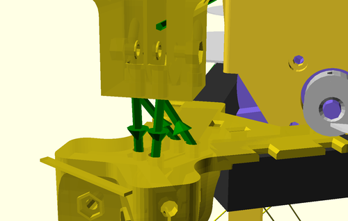
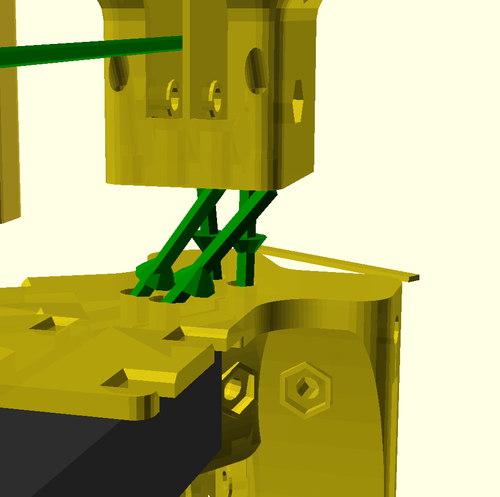
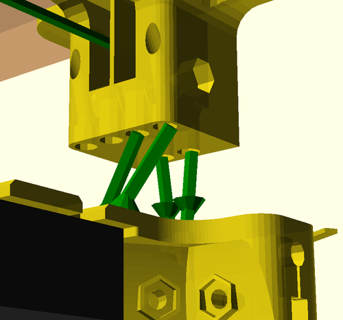
The three renderings above all show the corner closest to the B-motor on the ceiling unit. Mirror the setup at the opposite corner (closest to C-motor). The corner between the ODrives is a little bit easier because lines can be kept closer to vertical there but it also follows the same pattern.
The pair of lines farthest from the center are close to vertical. The pair of lines closer to the middle are slightly tilted, to enter the second bearing in the line verticalizer.
I use the eight shaped stop knot to attach the line to the spool, like this:
The ABC-lines are all terminated in the clamp at the top of the snaily snail:
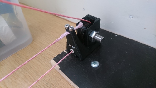
The D-lines are terminated in the ceiling unit. I terminate them with a wood screw, like this:
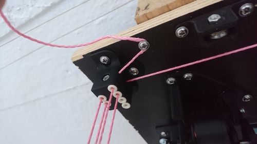
However, if the effector is very light on my particular machine, I sometimes use triple instead of quadruple D-lines. This lets me terminate the D-lines on the effector instead.
If you plan on doing the same, make sure to change your config.g accordingly.
The line saying M666 U2:2:2:4 needs to be changed to M666 U2:2:2:3.
Also, you'll have to make a similar 4->3 change inside simulation.py when you do your
auto-calibration later.
Screwing the ceiling unit onto the ceiling can be a bit challenging. I therefore added a hoisting system to my own HP4. See it in this tweet and this video. The little CAD models I used are shared here.
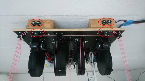
This has changed a lot between HP3 and HP4. A computer vision system called hp-mark has been developed to assist, and largely automate, the calibration process. The system has been built and proved, see this video:
Ok, this will be a bit messy. hp-mark is still in beta, and requires the user to be comfortable doing a few things via the Unix terminal. Our main goal is to be able to run the script called get_auto_calibration_data_automatically.sh.
The computer vision system is called hp-mark. It consists of
See the hp-mark repo,
and in particular the README.md and the doc directory for more guidance on how to set up
hp-mark.
The rest of this section will describe how to use hp-mark correctly with Hangprinter v4.
The get_auto_calibration_data_automatically.sh script is executed on the main computer.
It expects your camera-connected Raspberry to be available
at the ip called rpi in your /etc/hosts file.
It's also assuming your Duet3 connected Raspberry to be called duet3 in your /etc/hosts.
It's fine if duet3 and rpi are actually the same Raspberry Pi board.
Just configure them to the same ip address.
The Raspberry Pi needs the camera to be connected and calibrated (as described in the hp-mark repo), and it needs ssh to be enabled. Enabling ssh on a Raspberry pi might involve having to connect it to a display, and seek out Preferences -> Raspberry Pi Configuration in a graphical user interface.
The get_auto_calibration_data_automatically.sh script also needs a version of raspistill that matches your lens, or else your images' colors will be tinted. To get the one I use (matching my Arducam lo-distortion 45 deg lens), do
          $ ssh pi@rpi

          $ mkdir -p repos

          $ cd repos

          $ git clone https://github.com/ArduCAM/NativePiCamera.git

          $ cd NativePiCamera/bin

          $ chmod u+x raspistill_CS_lens
The duet3 official image is one comes with the camera disabled by default. To enable it do
          $ sudo raspi-config

          $ [Interface Options] -> [Camera] -> [Enable] -> [Reboot yes]
We also have some LED rings around the lens (I have 20. Don's use more than 20, since the Rpi's 5V pin can't output much current). To light up the LEDs, I used these pins on the camera-connected Raspberry:
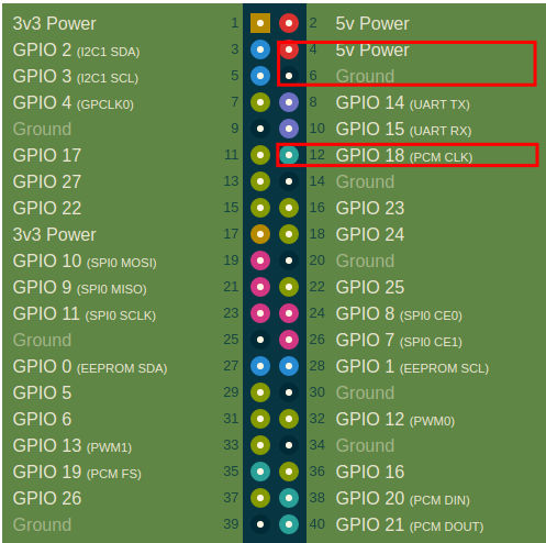
The Duet3 doesn't use any of pins 4, 6, or 12, although its connector covers them up. To work around the connector, you can created a distance between Rpi and the connector with nine short jumper wires like this:
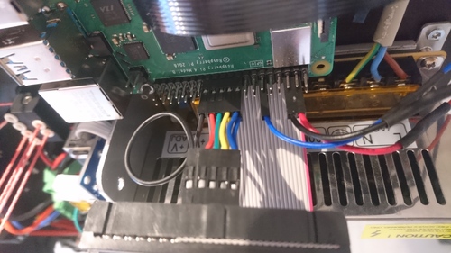

Connect the Raspberry's pins 17-25 with the Duet, as they would have been connected through the standard connector. Power the Raspberry Pi with a separate wallplug power supply. The official Raspberry Pi Power supply is recommended.
Here's how you get code that lights up the LEDs:
          $ ssh pi@rpi

          $ mkdir -p repos

          $ cd repos

          $ git clone https://gitlab.com/tobben/rpi_ws281x.git

          $ sudo apt install python3-pip

          $ sudo pip3 install rpi_ws281x
On your main computer, try to take an image and analyze it:
          $ cd <path-to>/hp-mark/use

          $ ./use_ssh.sh --show result
If everything worked, the LEDs should have flashed, an image should be taken, downloaded, analyzed by your hpm program, and the result (an image) should be shown on the screen, like this:
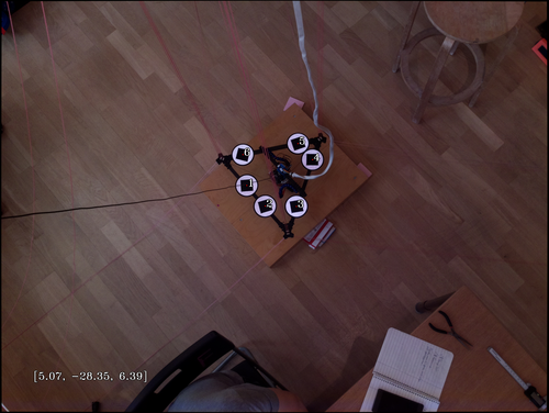
The console output should be similar to this:
          $ ./use_ssh.sh --show result

/home/pi/repos/hp-mark/use

Captured image remotely: /home/pi/repos/hp-mark/use/images/DiUBh.jpg.

Copies home:

DiUBh.jpg 100% 4512KB   4.9MB/s   00:00

/home/tobben/repos/hp-mark/use

Will execute:

../hpm/hpm/hpm ../hpm/hpm/example-cam-params/loDistCamParams2.xml ../hpm/hpm/example-marker-params/my-marker-params.xml ./images/DiUBh.jpg --show result

[5.22761, -28.5536, 6.5542];
At the time of writing (March 30, 2022), there are two under-documented but highly useful features in hp-mark.
One is the --bed-reference feature.
It let's you had a set of six markers on the print bed, analogous to the six you already have on the effector.
Measure their positions, and include them in my-marker-params.xml, just like you did with the
effector markers.
They give you much more stable measurements in case your camera has moved slightly since your last
--camera-calibration.
The other useful feature is called --try-hard.
It makes measurements a bit slower, but more stable.
Do ../hpm/hpm/hpm --help for definitive up-to-date info about your executable's features.
The get_auto_calibration_data_automatically.sh script will use your camera to take measurements, and wait for you to move your effector around between measurements. For moving your effector my hand, it's very useful to have the motors in torque mode. You'll probably want to have the Torque_mode macros installed into your macro folder on the Duet3.
Play with the torque mode scripts in the web interface before running the full calibration script. For example, in the web interface, go to the console and to set motor A in torque mode, with 0.02 Nm of torque. Feel the spool gently with your and confirm that the motor tries to pull line inwards onto the spool
M98 P"/macros/Torque/Torque_mode_all" A0.02
Repeat for all motors ABCD. (In ReprapFirmware 3.5, the unit of the argument A<arg> will change from Nm to just N. It will print the Nm applied into the WebGui console.)
With camera and torque mode macro in place, if all the stars align, it should be possible for you to collect the calibration data like this:
$ cd path/to/hp-mark/use

            $ ./get_auto_calibration_data_automatically.sh --show result --bed-reference --try-hard
The --show result option will make hpm stop and show you each measurement when it's done, and wait
for you to press
Enter before it continues.
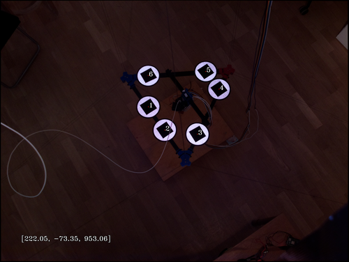
--show result option enabled.
After collecting 25 data points (don't worry if a few were unsuccessful or printed a warning), it prints out the data it has collected in a format that copy/paste friendly for the next script we're going to use: simulation.py.
For detailed documentation on how to use the script, see its repo.
Hopefully it will output a perfect set of M669 and M666 commands, to copy/paste into your config.g.
For anyone who have reached this far: I salute you. Reach me via Discord and tell me you need the auto calibration stuff, and I'll up-prioritize automating further and documenting better.
I've published the Prusa Slicer configs that I use at gitlab.com/tobben/prusaslicer-configs.
Before you start a large print, it's recommended to check if your model fits the print volume or not. This is done with line-collision-detector, a tool that is developed specifically for Hangprinter build volume verification.
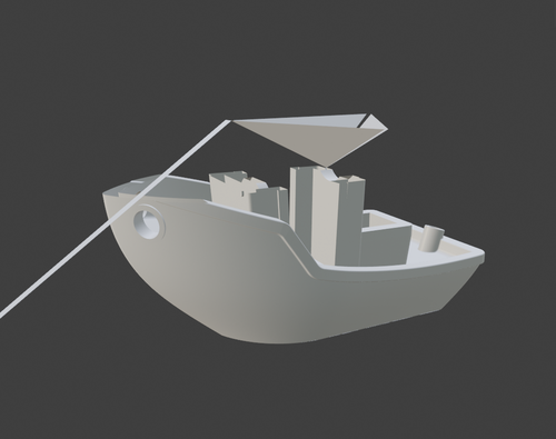
Please note that many slicers will auto center the model before slicing it. line-collision-detector will not do that. Since you probably want to check if the centered version of your model collides with lines or not, it's recommended to first import your model in the slicer, and then export it from the slicer as an stl, and then run it through the line-collision-detector.
Building, mounting, calibrating, and running a HP4 is a big undertaking, and many of the steps are sparsely documented, but you are not alone. Be sure to check out the resources, there are some quite good ones.
If you spot an error or a missing link in the documentation, then please fix it and contribute the fix back to the repo. But also, do come by the Discord and say hi, or have a chat via Gitlab merge request or issue.
- tobben 👷
The raw text source of this manual is published under the GPL-2.0 license, and is being maintained in the hangprinter-org repo. All images and videos are also published under the GPL-2.0.