Welcome to Hangprinter version 3 hardware assembly.
Please click on the pictures to see larger versions.
The below instructions assume you have completed the sourcing step.
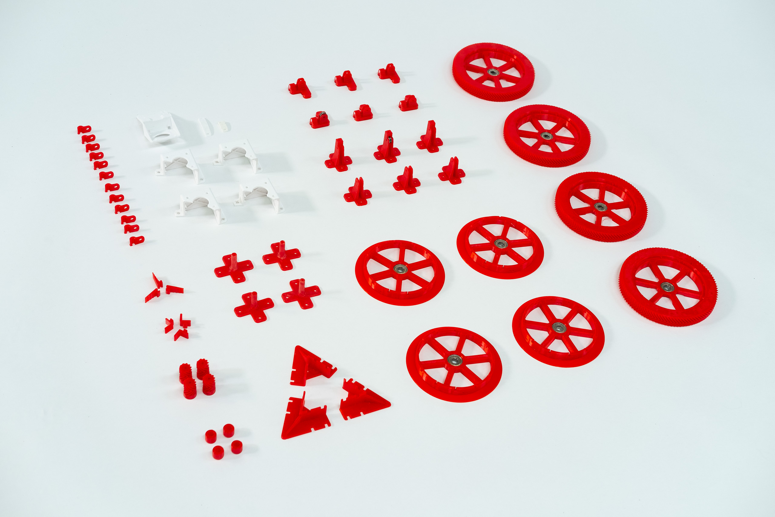
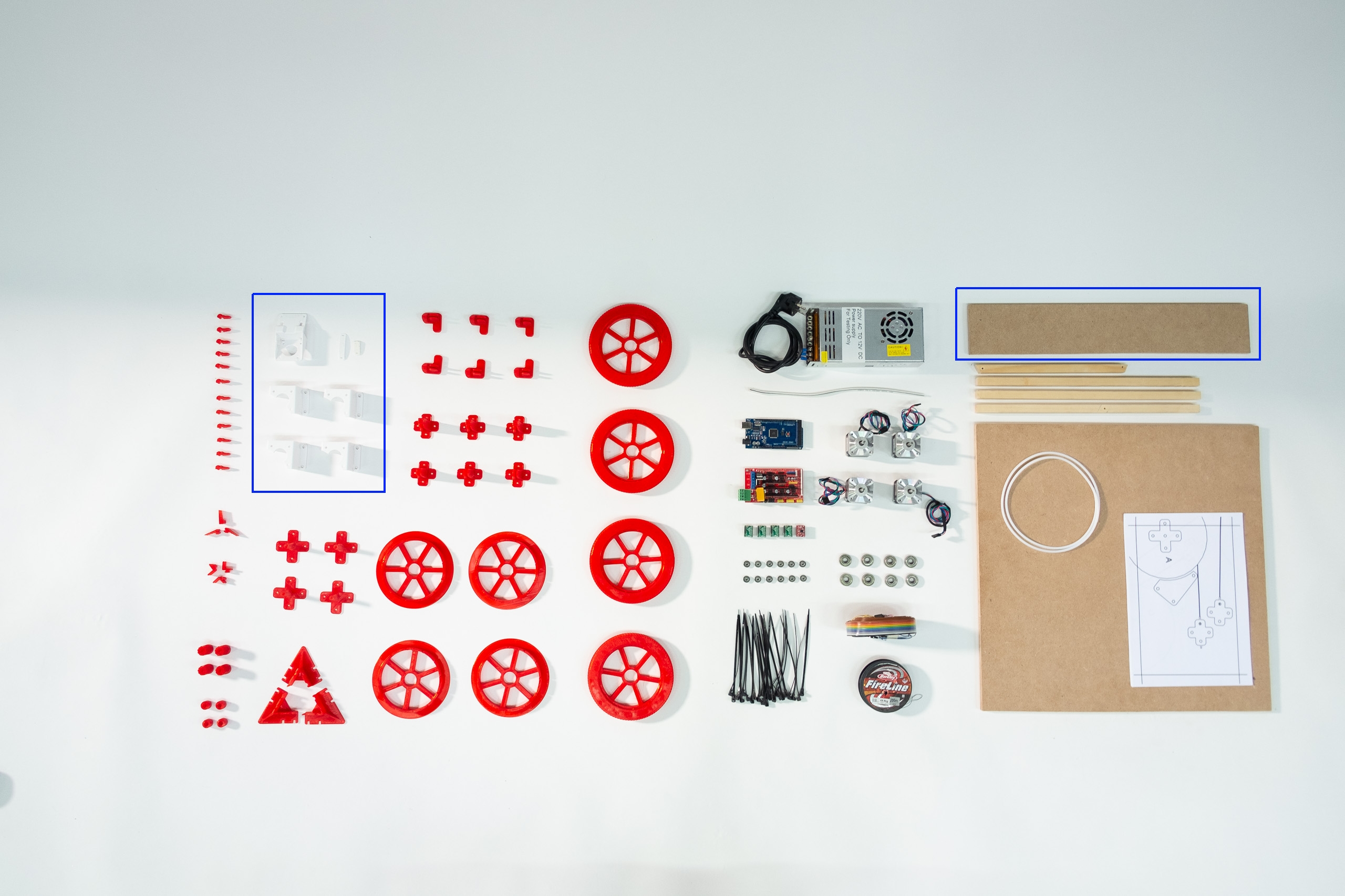
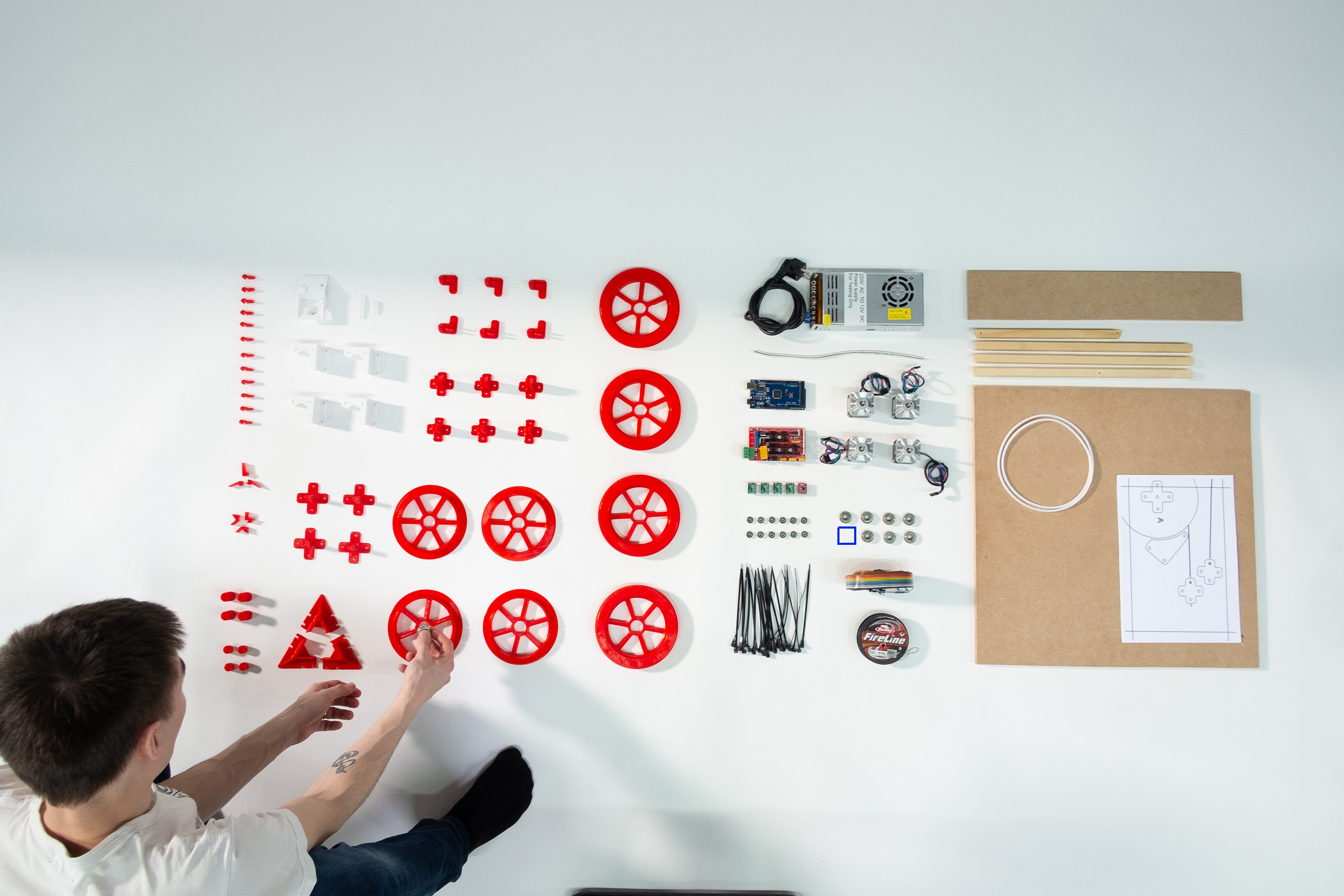
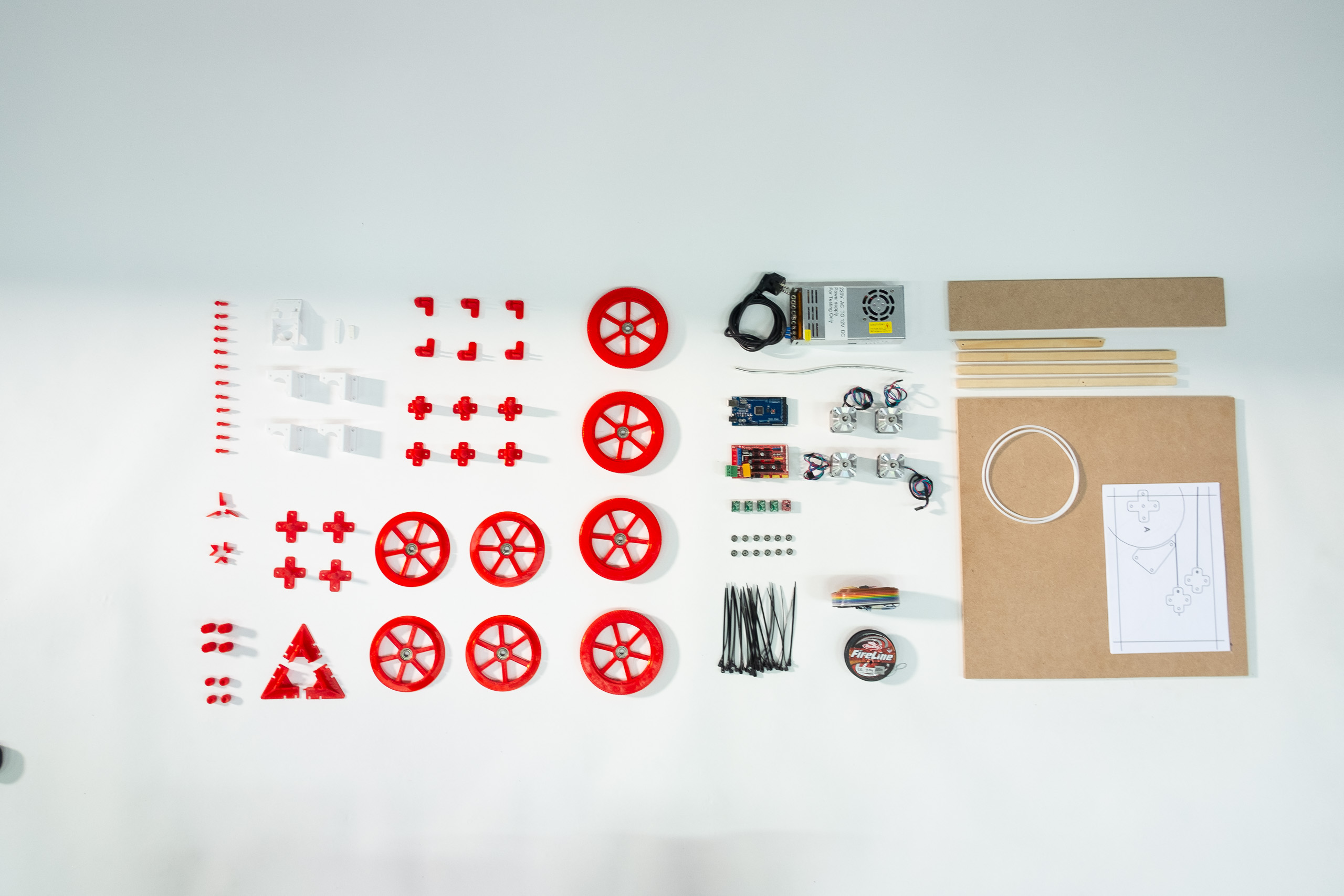
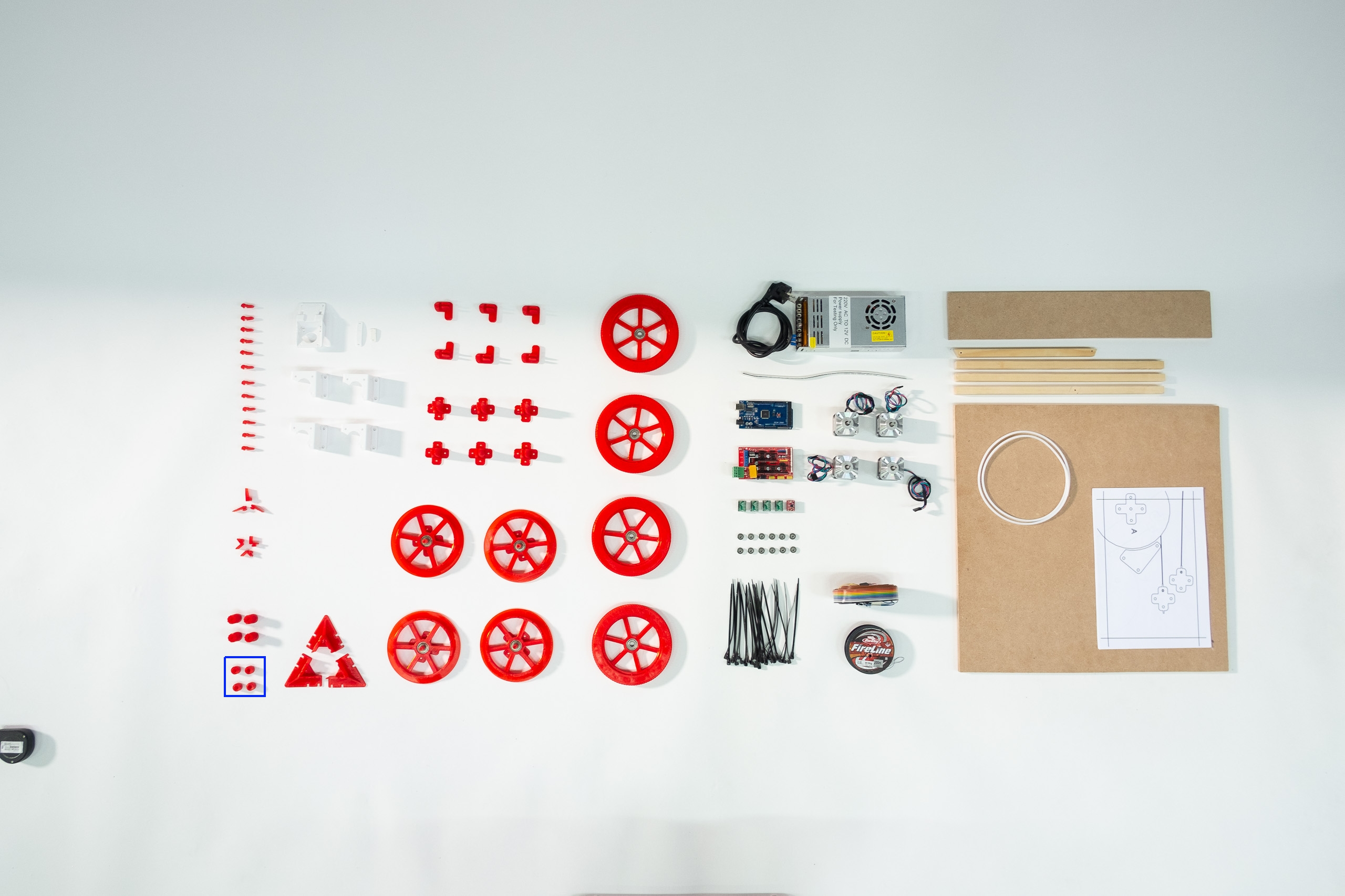
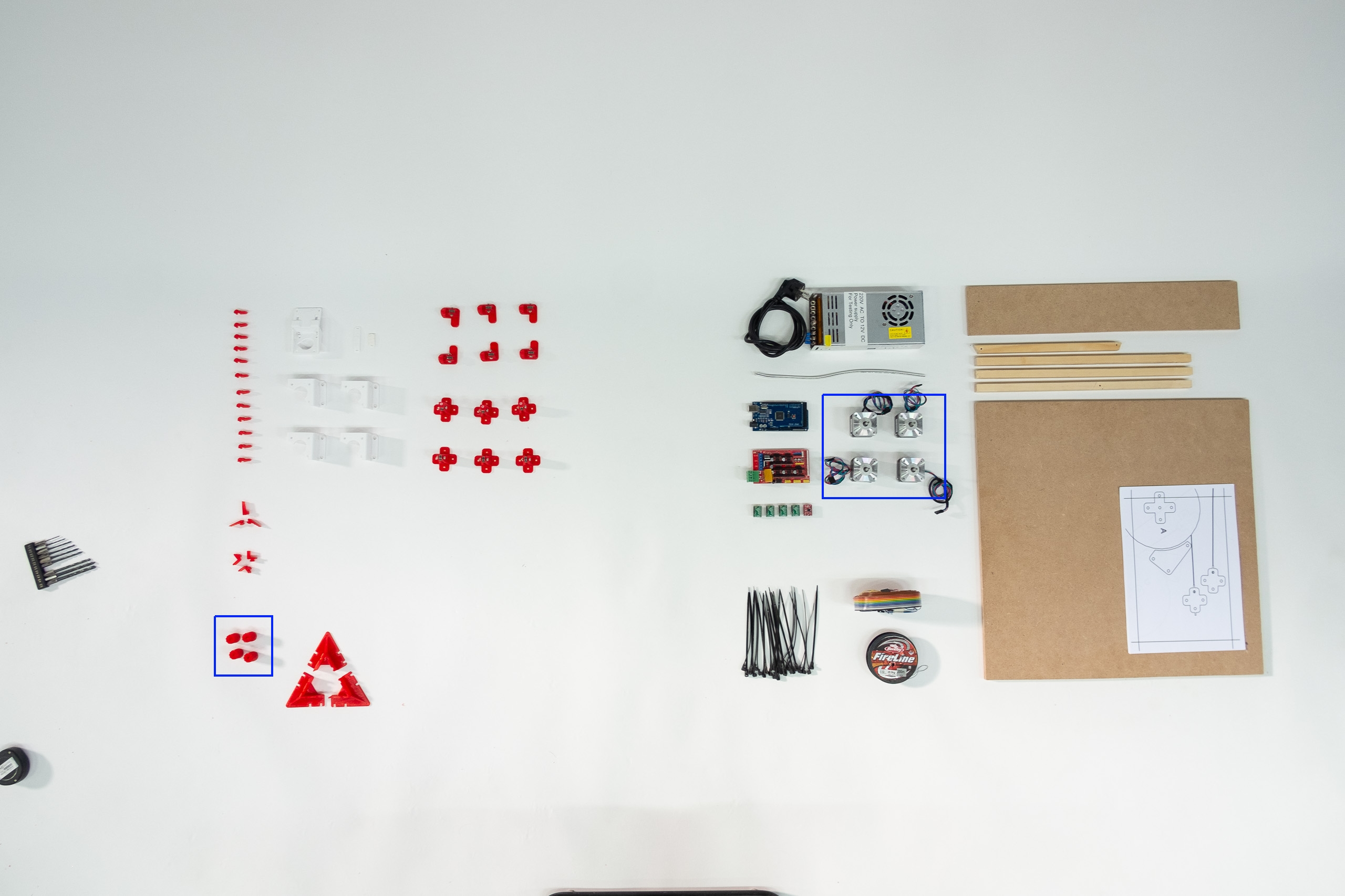
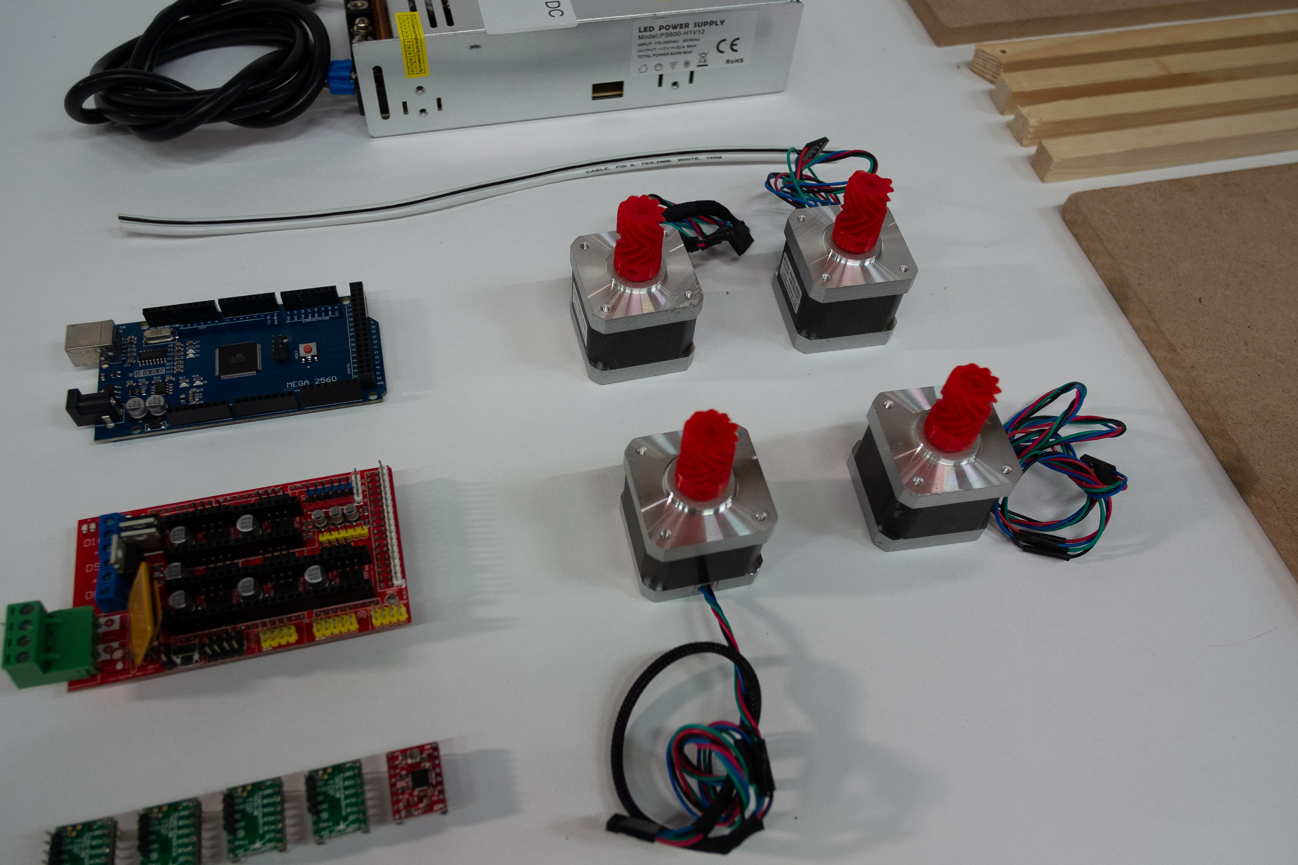
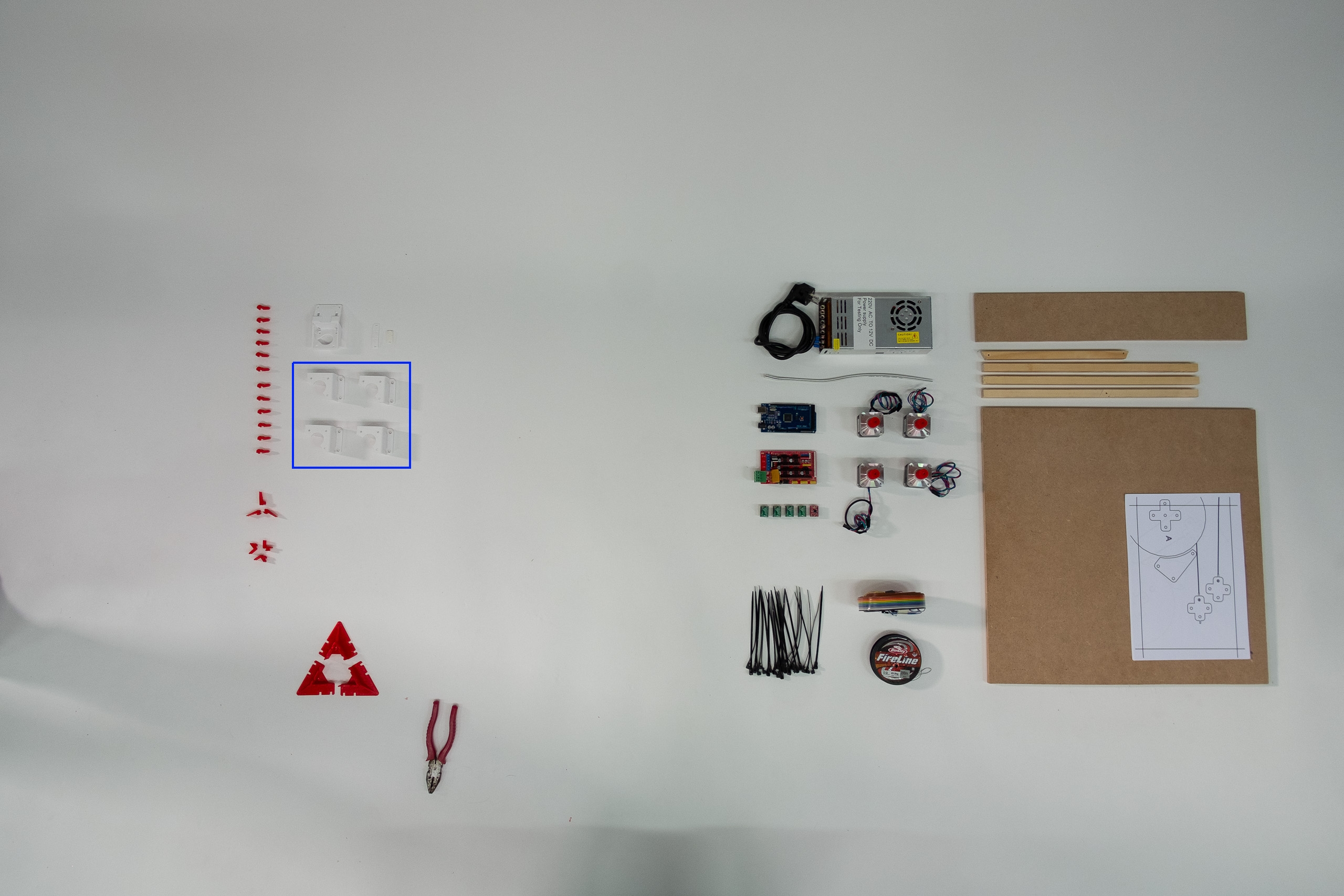
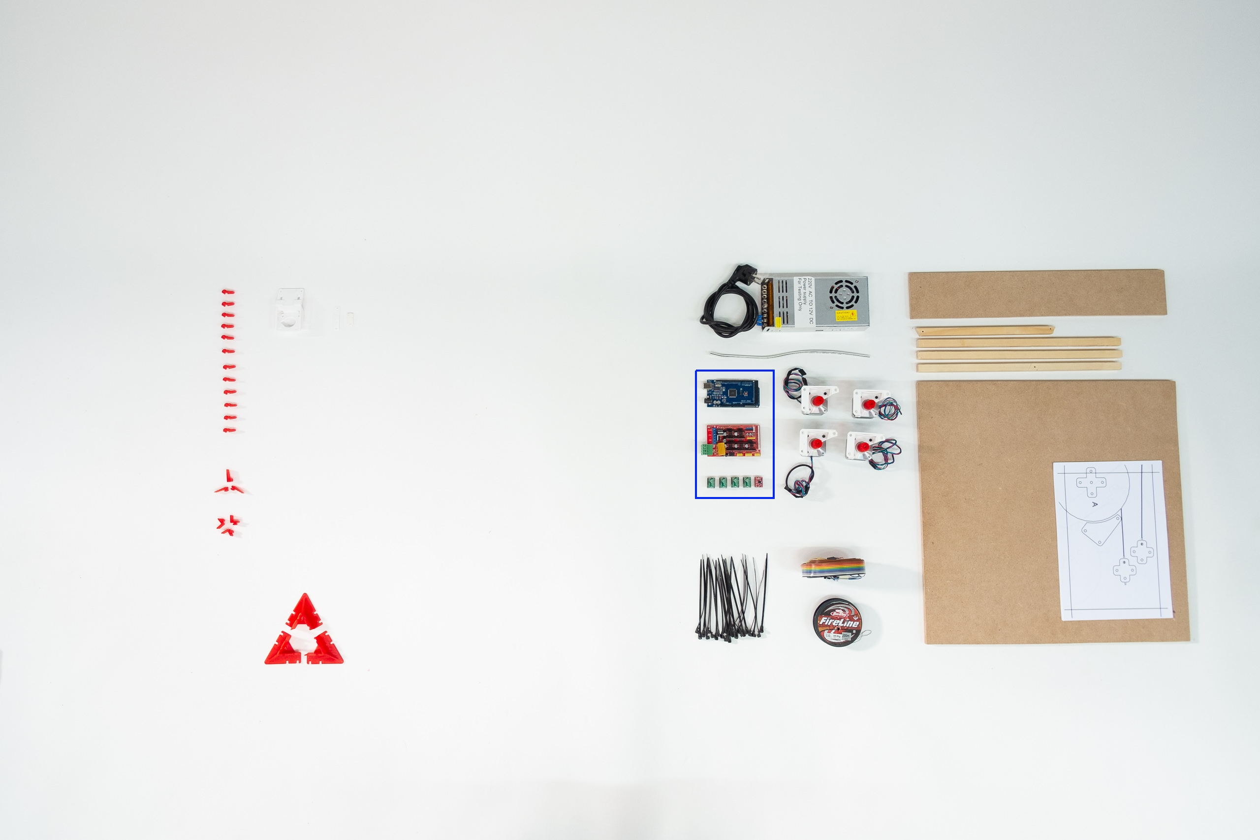
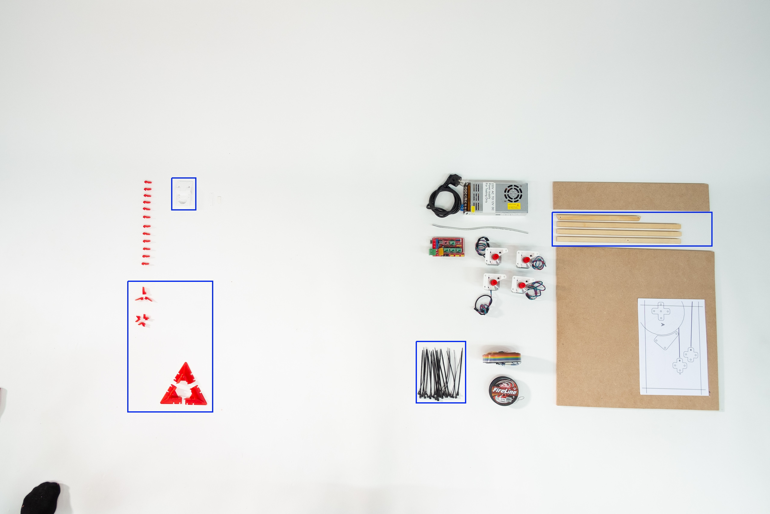
Hardware for a non-SmartStepper build, excluding USB cable and screws.
Note that the rectangular sheet material is for building ABC anchors.
They should be a stack of three.
The white printed parts will be in contact with motors.
Print them in a heat resistant plastic in case your motors ever run warm.
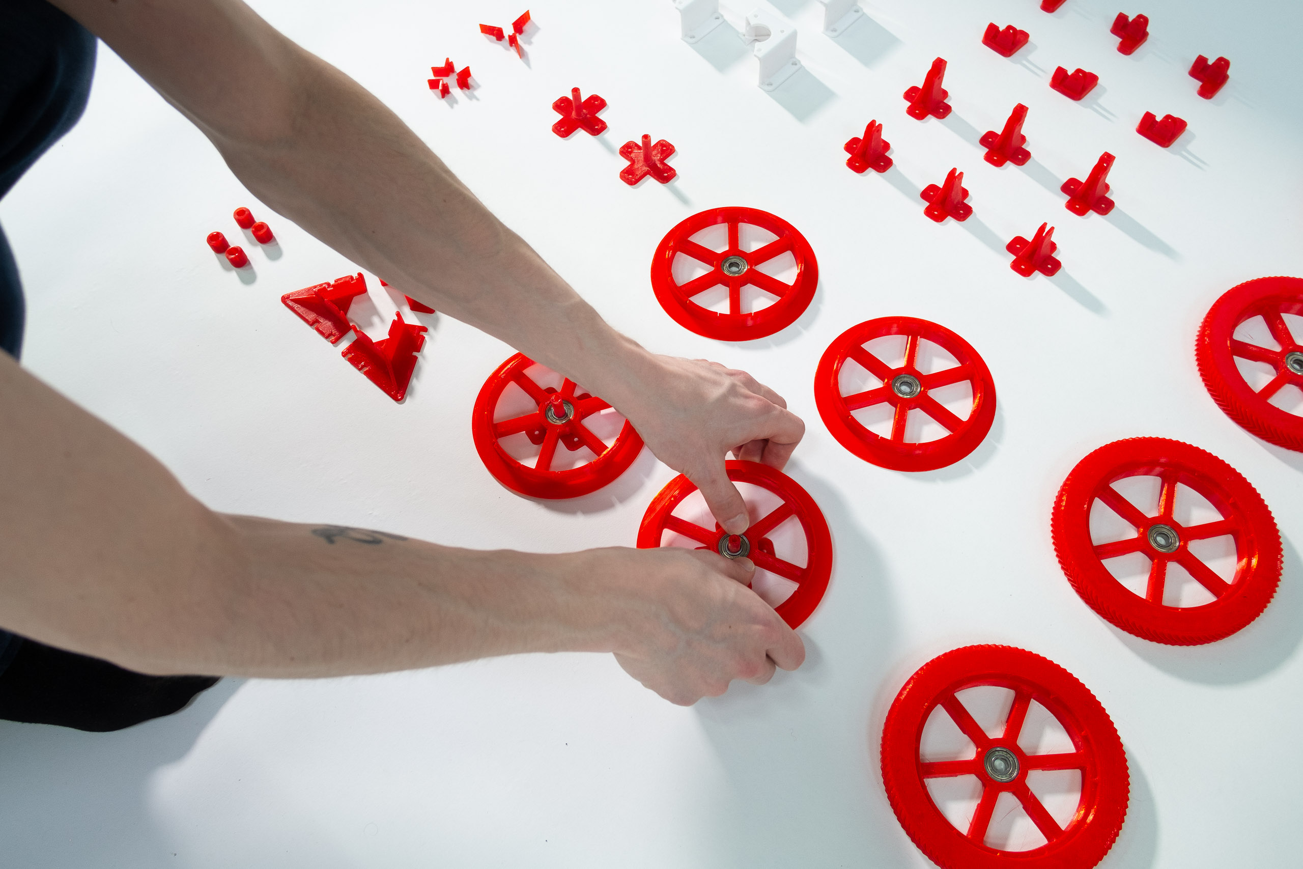
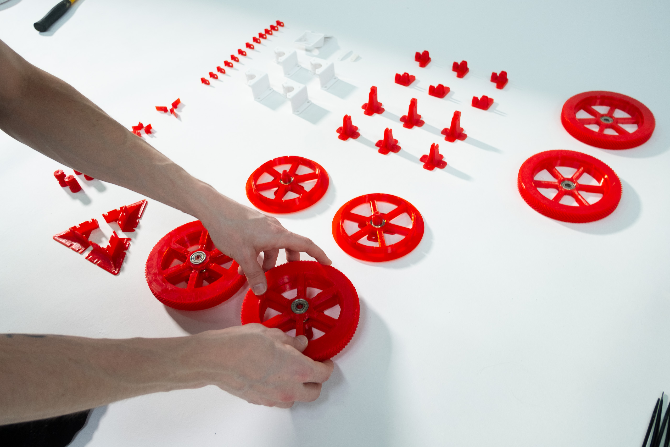
Push spools and spool gears onto the 608 bearings.
Repeat for all spools and spool gears.
Push spools with 608 bearings onto spool cores.
Now grab your spacers.
... and check that they push fit nicely onto your spool cores.
Now might be a good time to measure your spools' radii with a pair of calipers.
Note the radii onto the spools themselves.
This will be needed for firmware calibration later on.
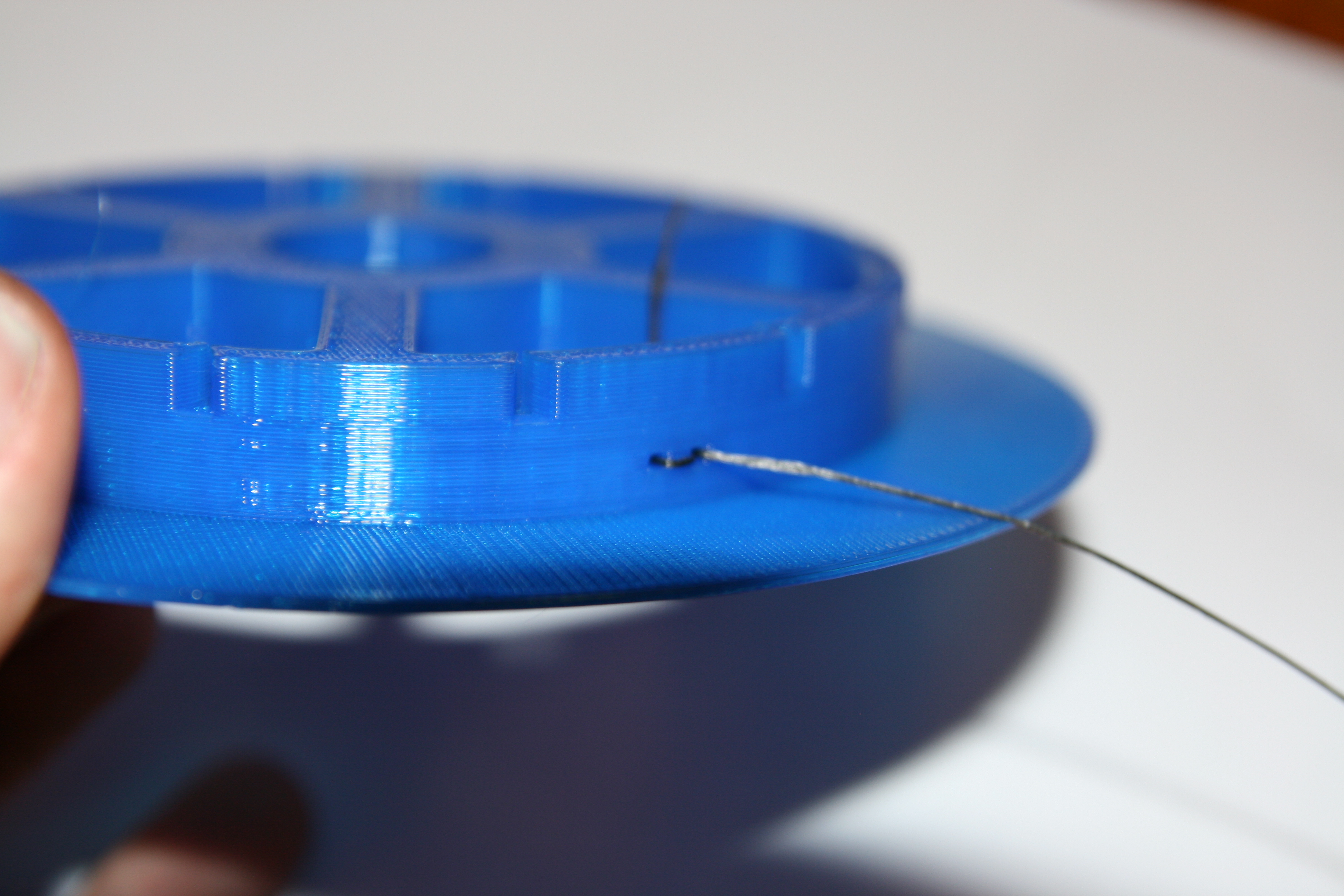
It might also be a good time to attach lines to your spools.
Nine lines are required to drive the printer.
By default, three of them are 4m long, the remaining six are 7.5m long.
Attach the 4m ones onto one spool.
Attach pairs of 7.5m ones onto the remaining three spools.
A more detailed guide on choosing line lengths is found here.
If you use custom line lengths or line thickness, you need to specifiy this in firmware settings later on.
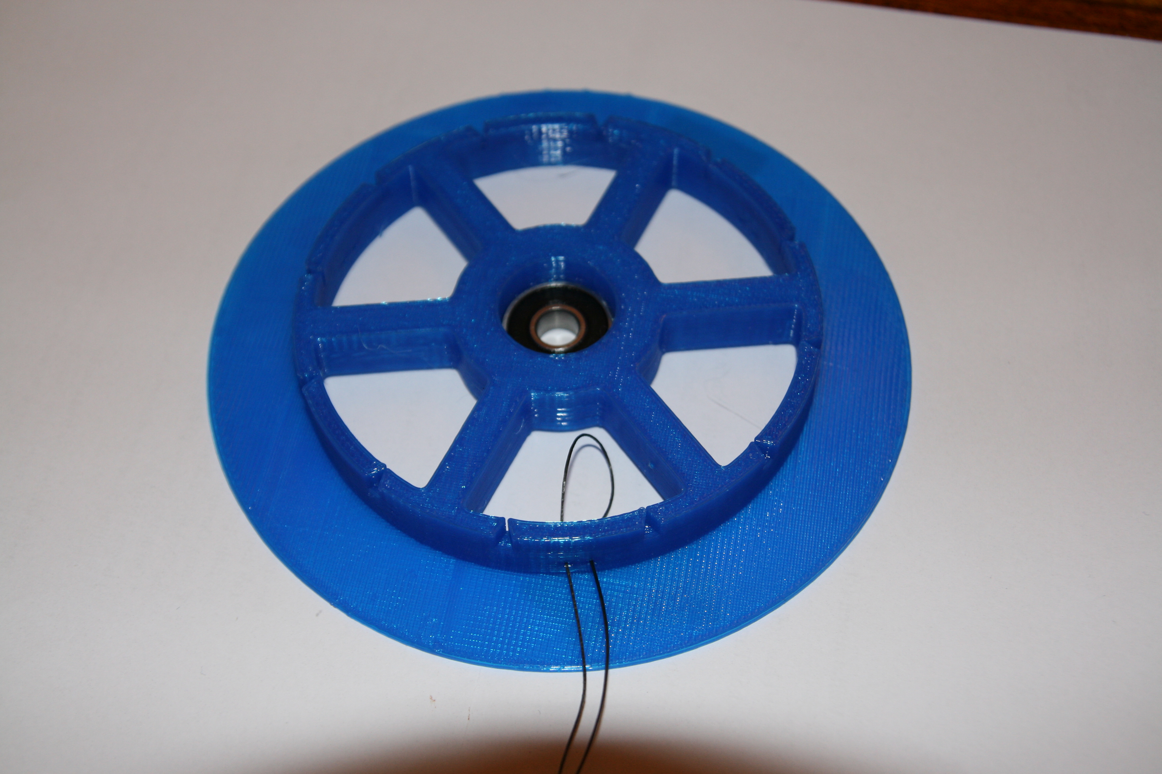
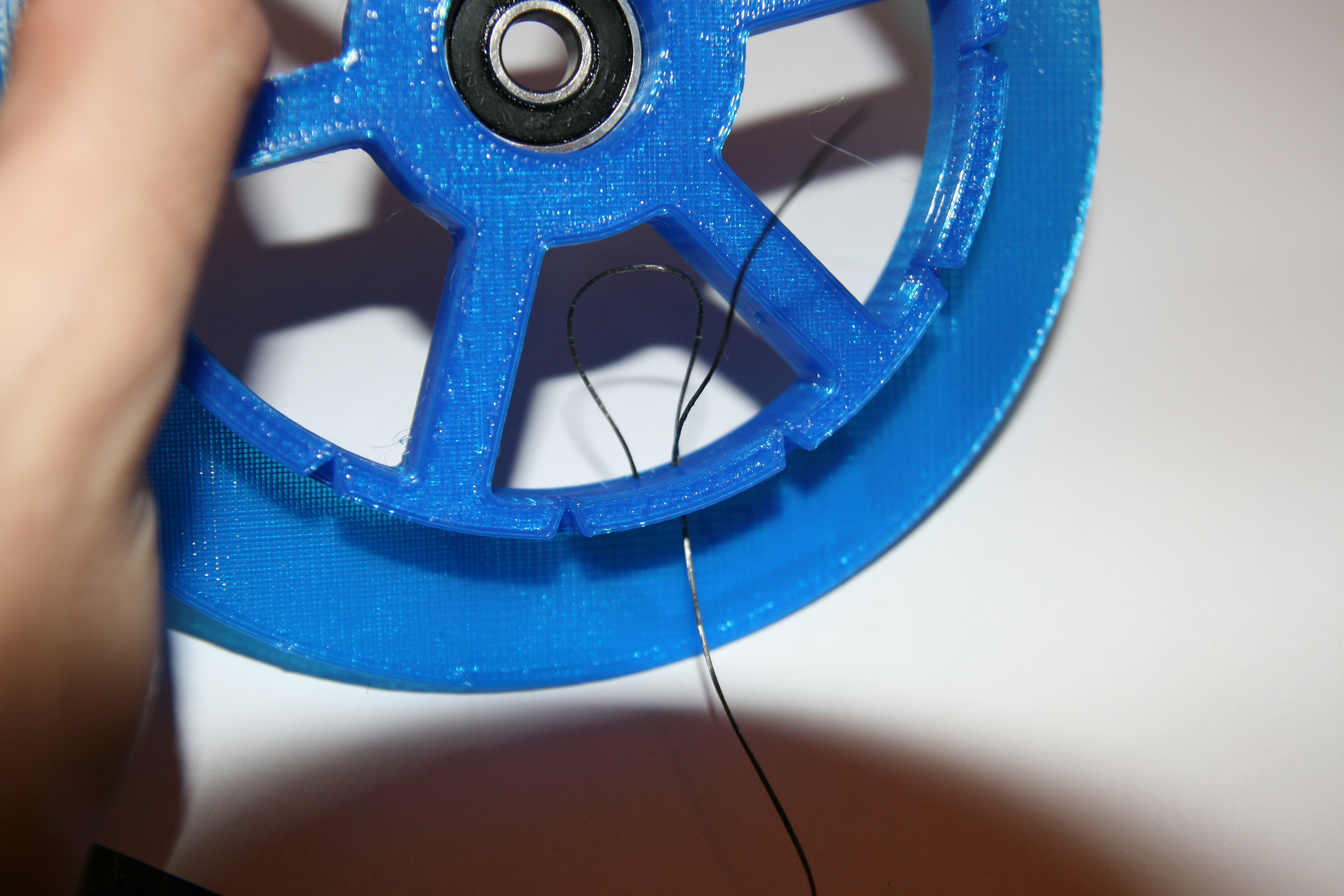
This is how you tie your line to your spool:
Thread a loop in through the right spool wall hole and back out of the left hole.
Thread your line through the right hole again.
Tighten from the inside. Leave plenty of loose thread on the inside.
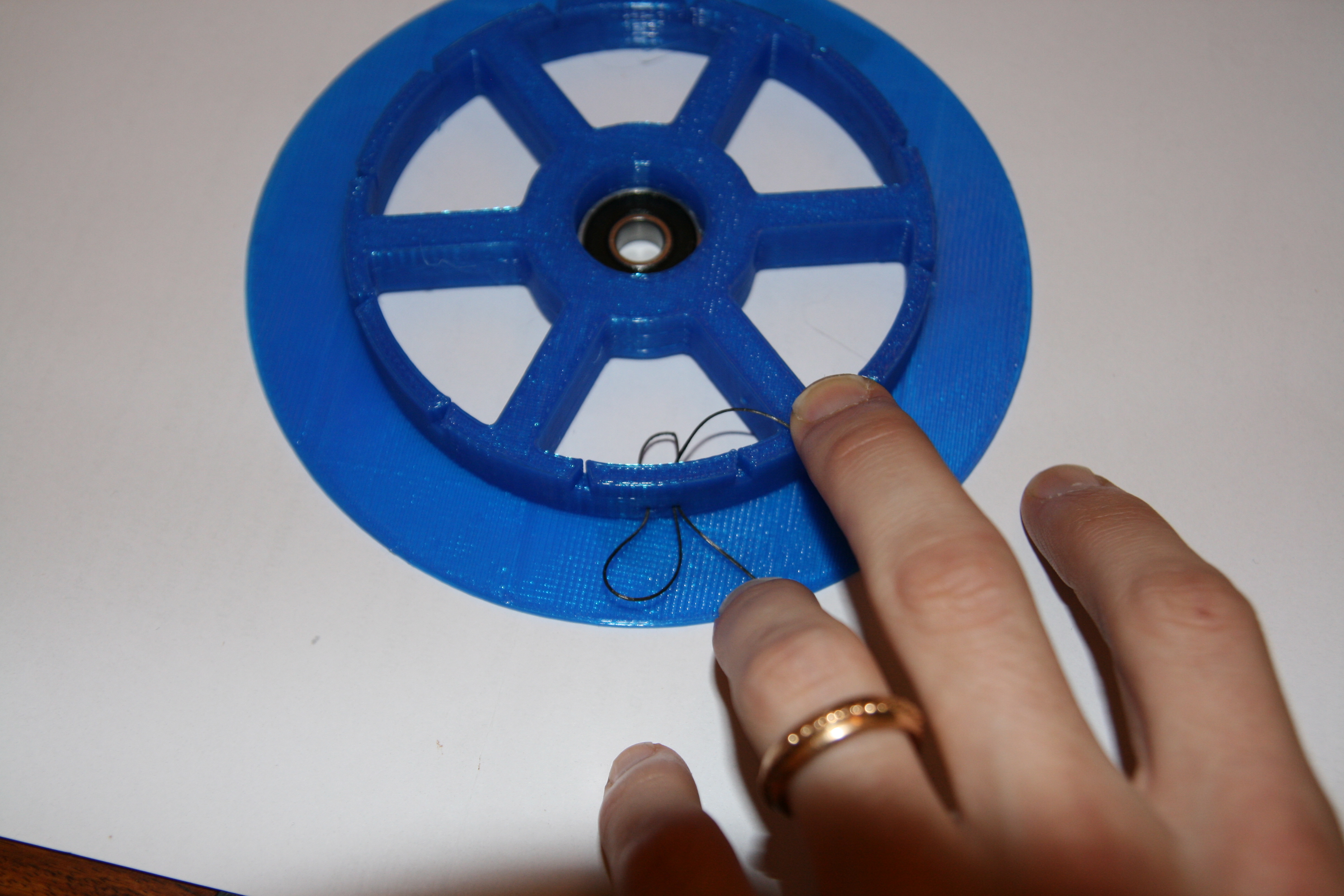
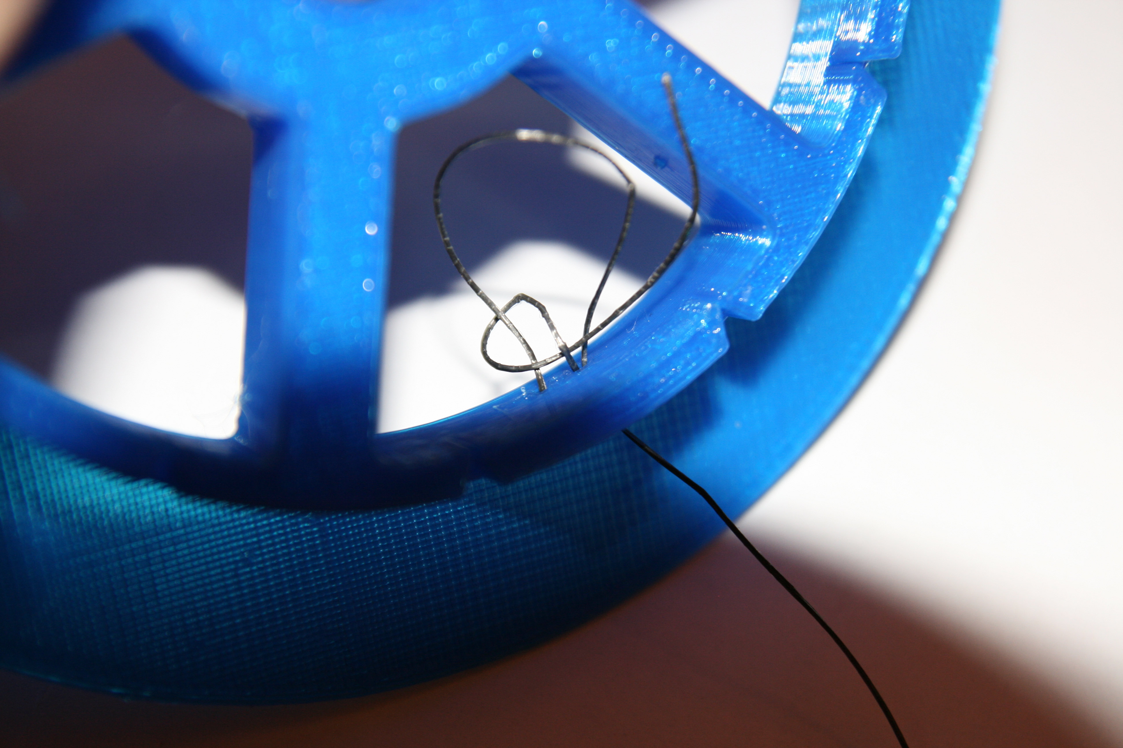
Make a simple hitch around the left leg of your loop.
Close-up of the same hitch.
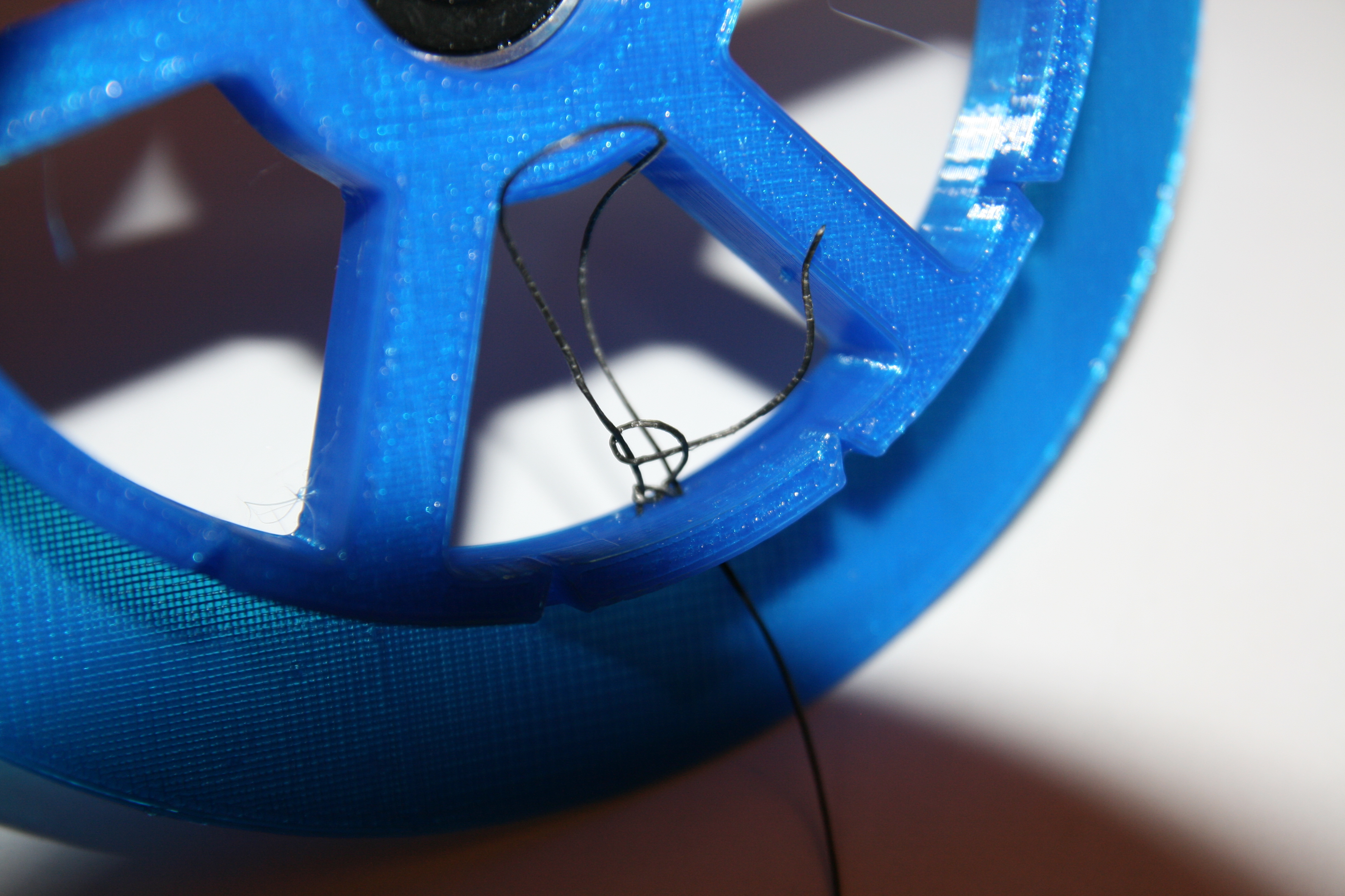
Make another hitch above the previous one.
Make three hitches in total, so one more after this one.
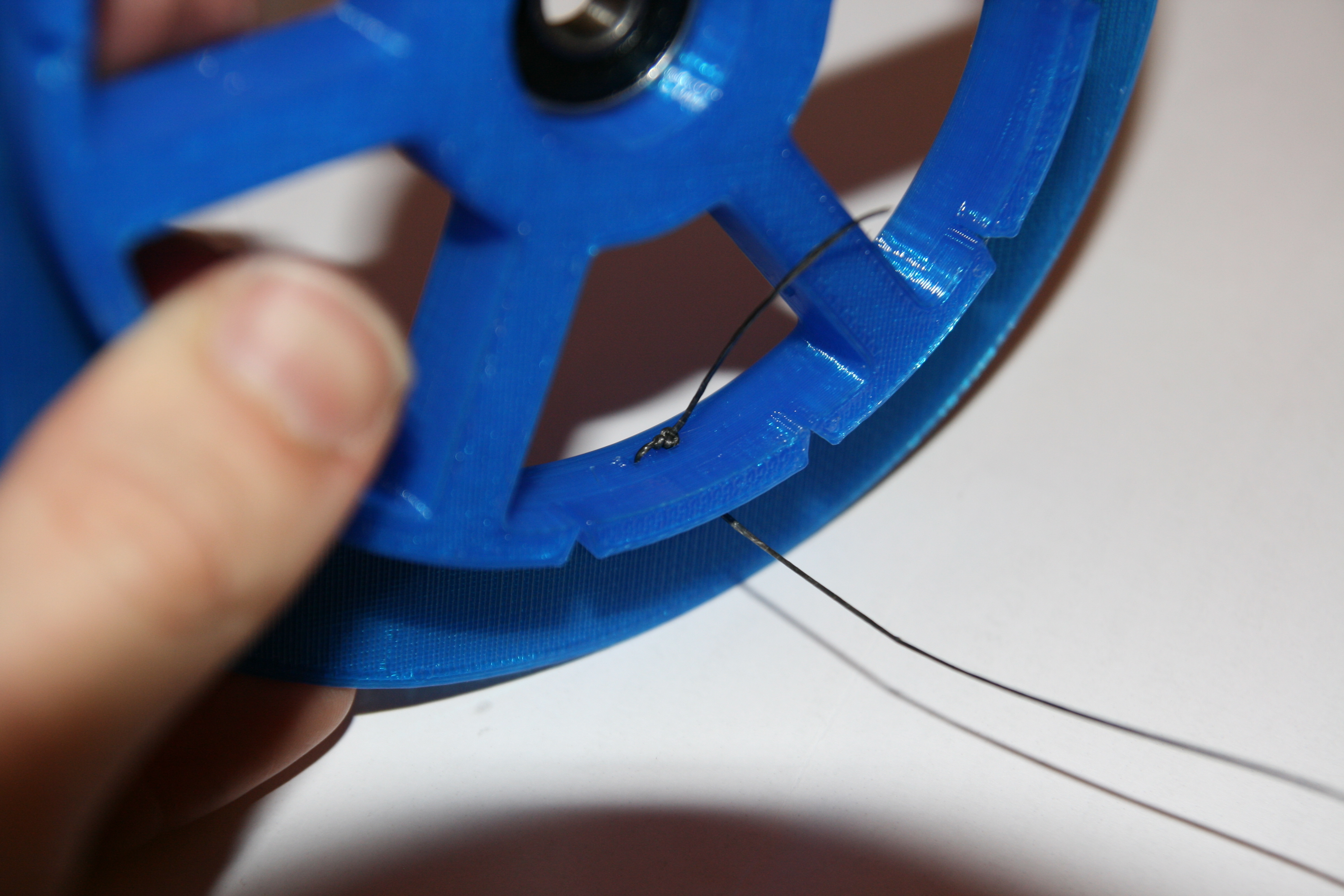
Tighten your hitches by pulling the loop's left leg and the line's loose end.
Then pull from the spools outside to see if you knot holds.
The outside of your spool should now look like this.
Check that the spool gears fit nicely onto the spools.
Note that the two spool+spool gears are mounted upside down in this picture.
The hatches in the spool gear spokes are there to allow space for the four screw heads later.
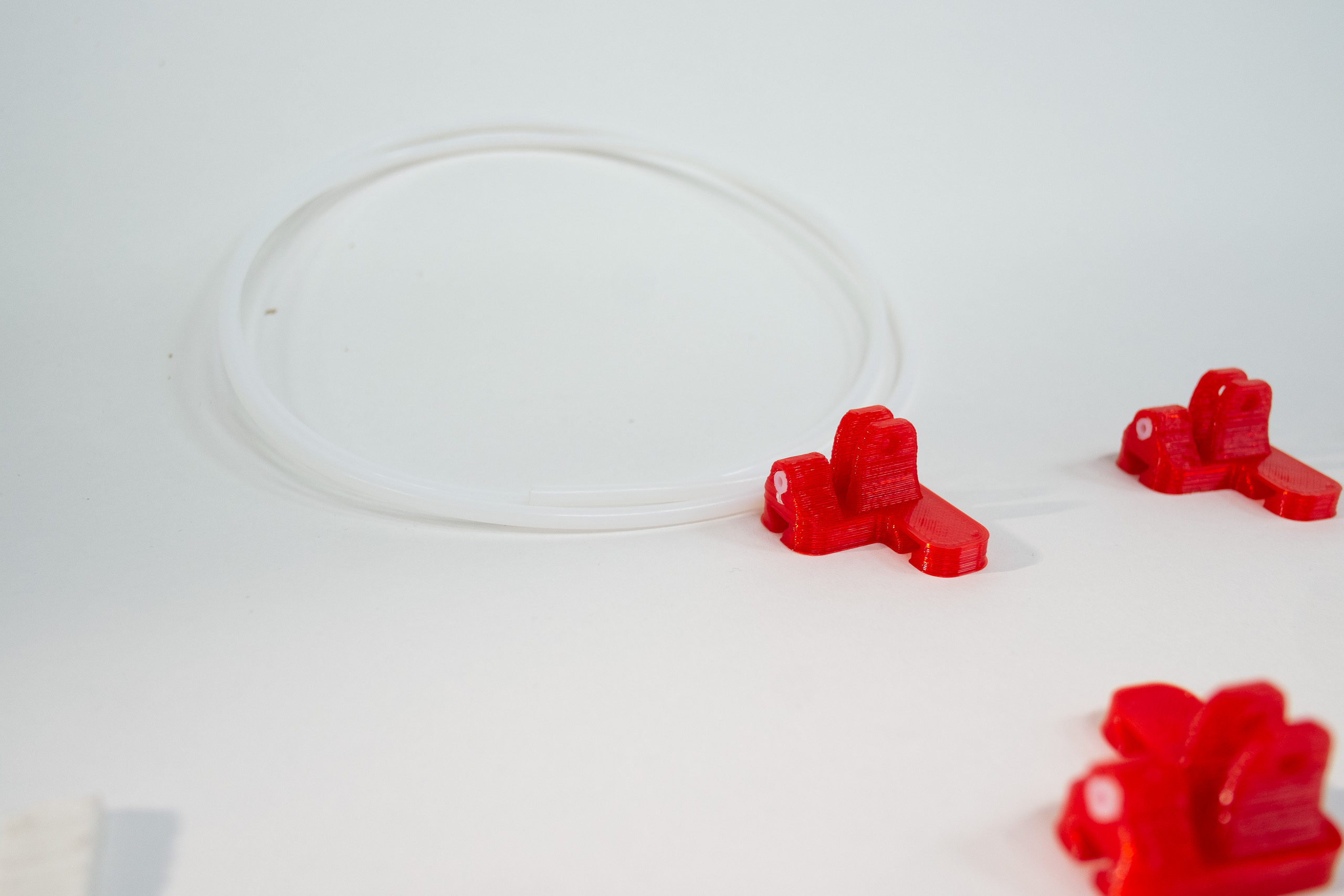
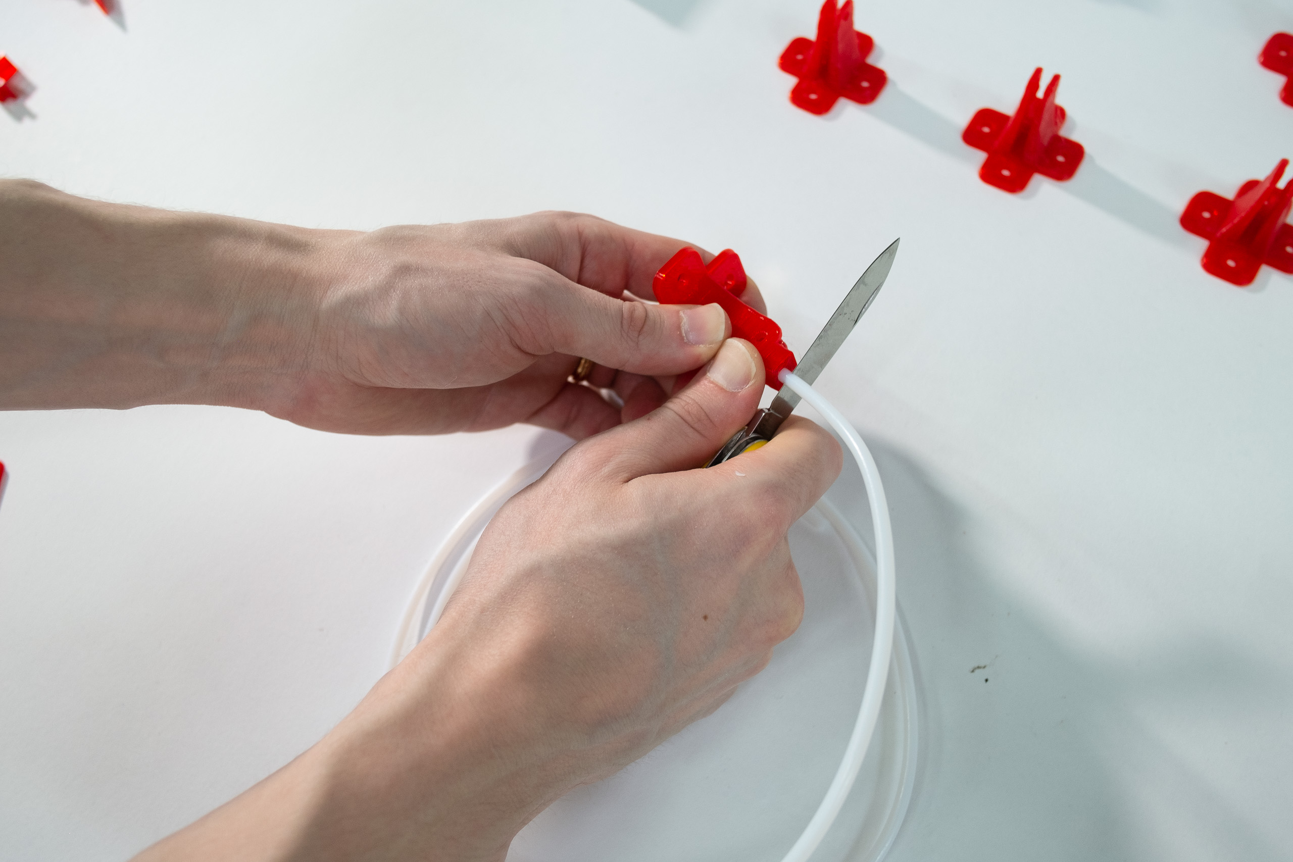
Insert PTFE tube into anchor linerollers and cut flush with front.
Do the same with D-linerollers.
PTFE tubes should fit tightly in D-linerollers. Push them in the like this.
PTFE tubes inserted.
Mount v-groove 623 bearings into all linerollers.
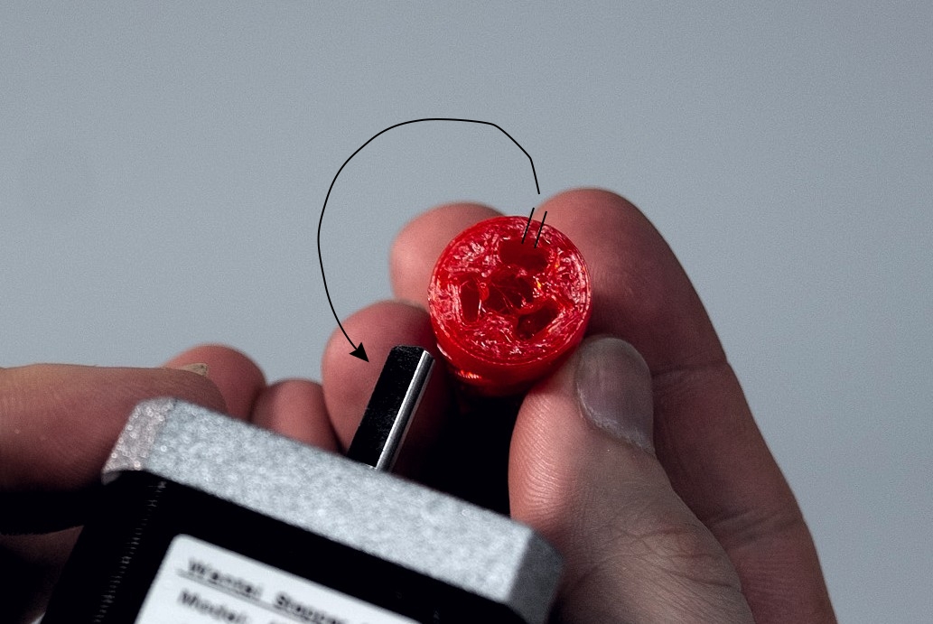
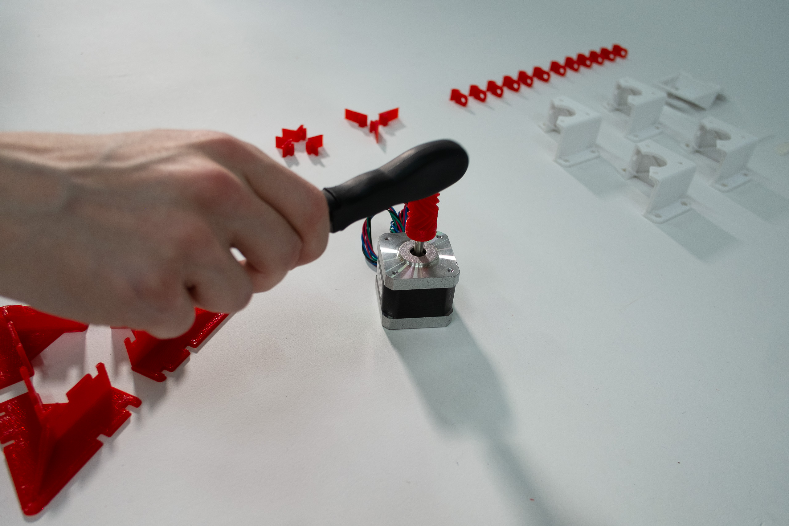
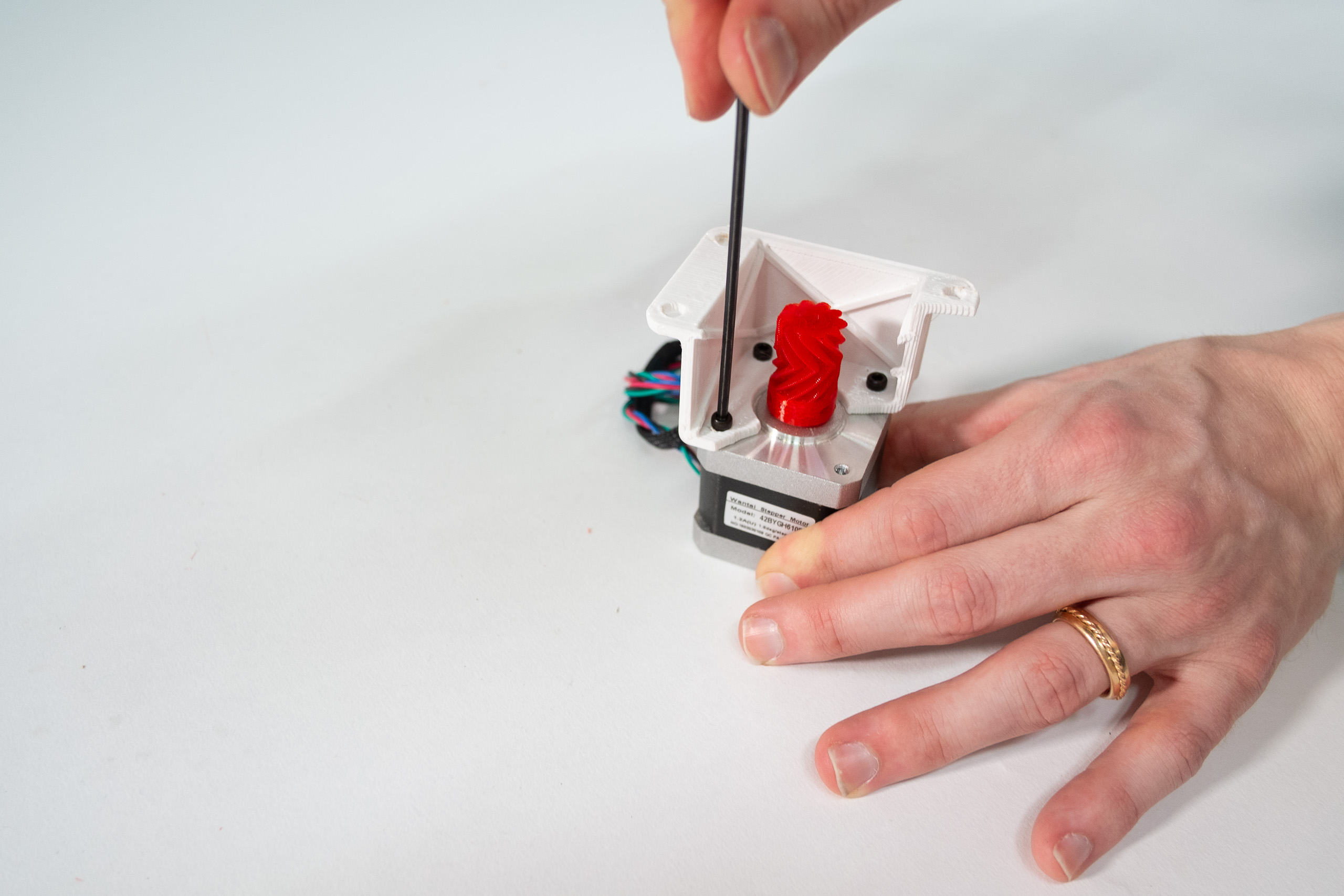
Now grap your motors and motor gears.
The motor gears have D-shaped holes and a notch to help you align them with the motors shafts.
Hammer the motor gear gently in place with many small hits of a light, soft, and rounded object.
Don't hit hard.
If your motor gear holes are too tight, drill/file it wider, or just print new ones.
If your motor gear holes are too wide, insert nuts from below and tighten with set-screws.
Gap between motor gear and motor should be ca 1 mm.
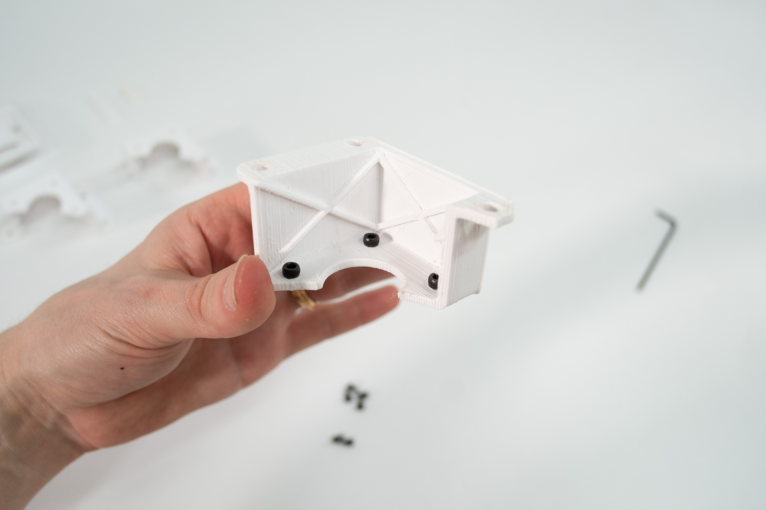
Now grab your motor brackets.
Insert the three screws in their holes first.
It will be more fiddly to do later.
Mount motor brackets onto motors.
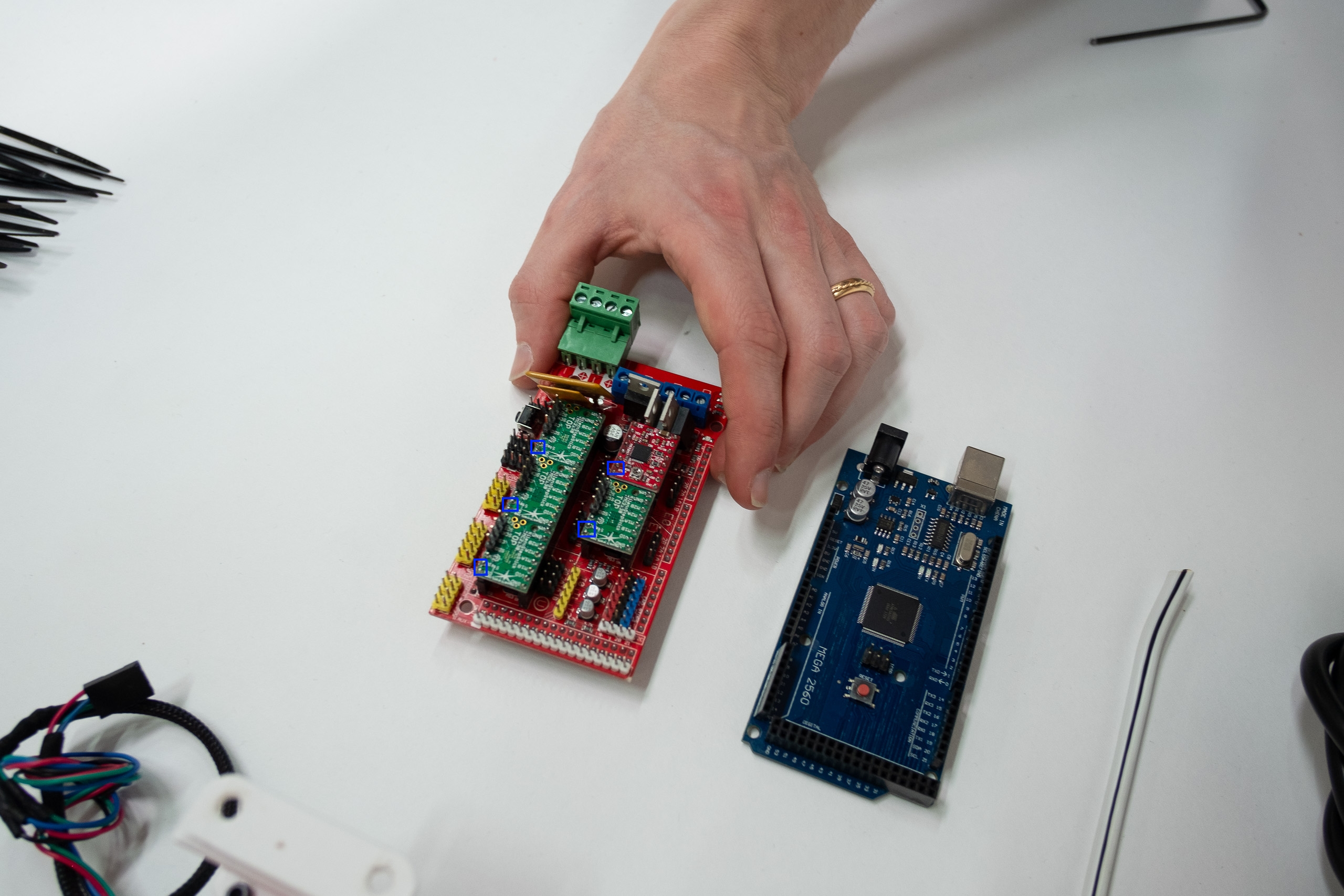
Now put together your electronics.
It's recommended to use SmartSteppers on the A, B, C, and D-motors, even though stepsticks are shown in the
picture.
See SmartStepper assembly instructions.
Insert your drivers' step/dir into the RAMPS board's step/dir outputs.
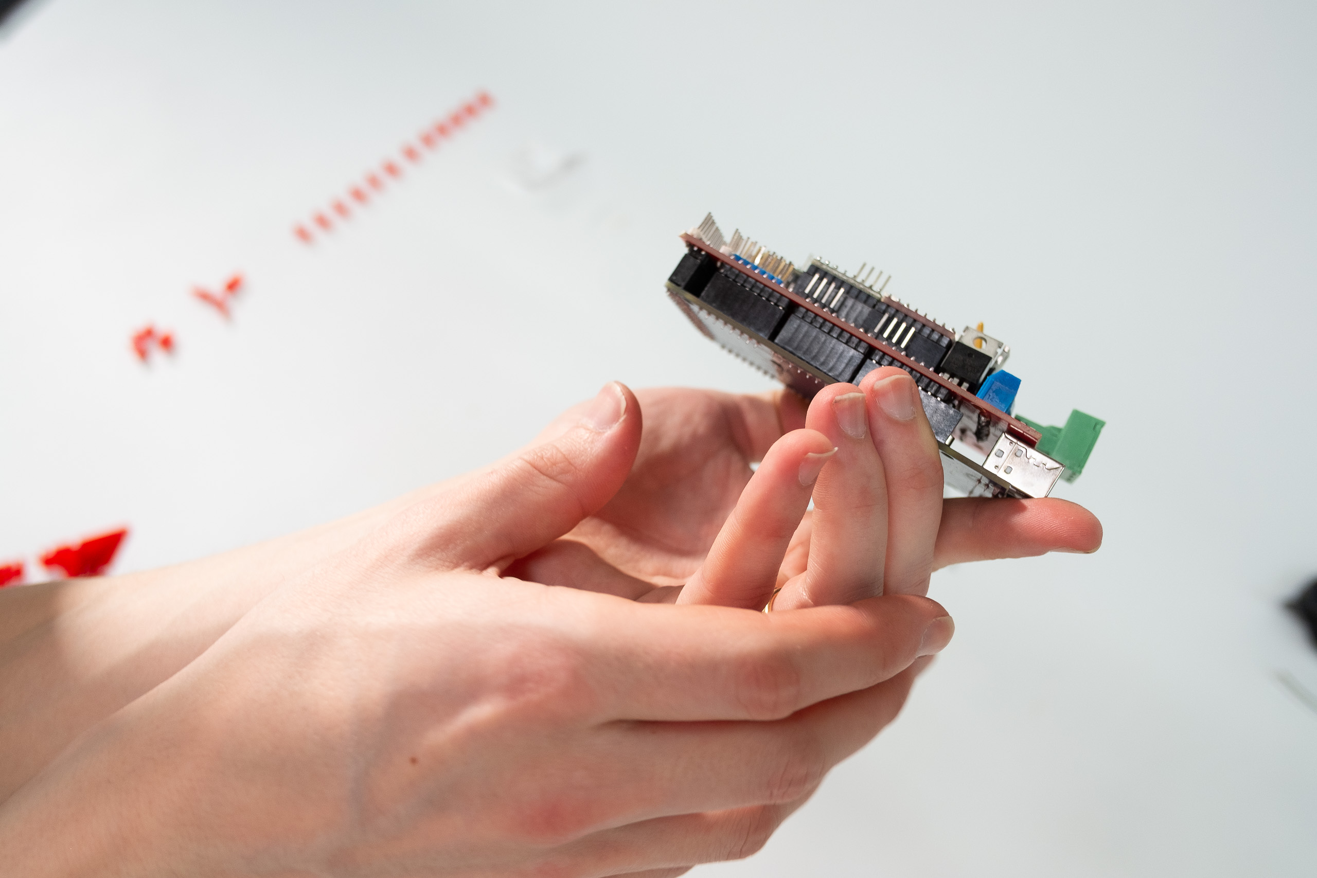
Mount your RAMPS shield tightly onto your Arduino Mega.
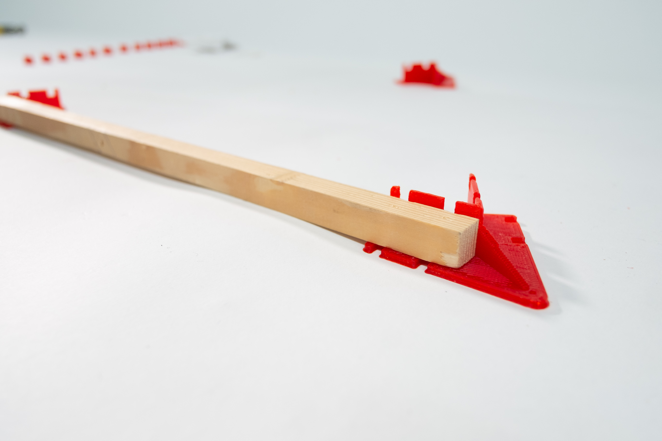
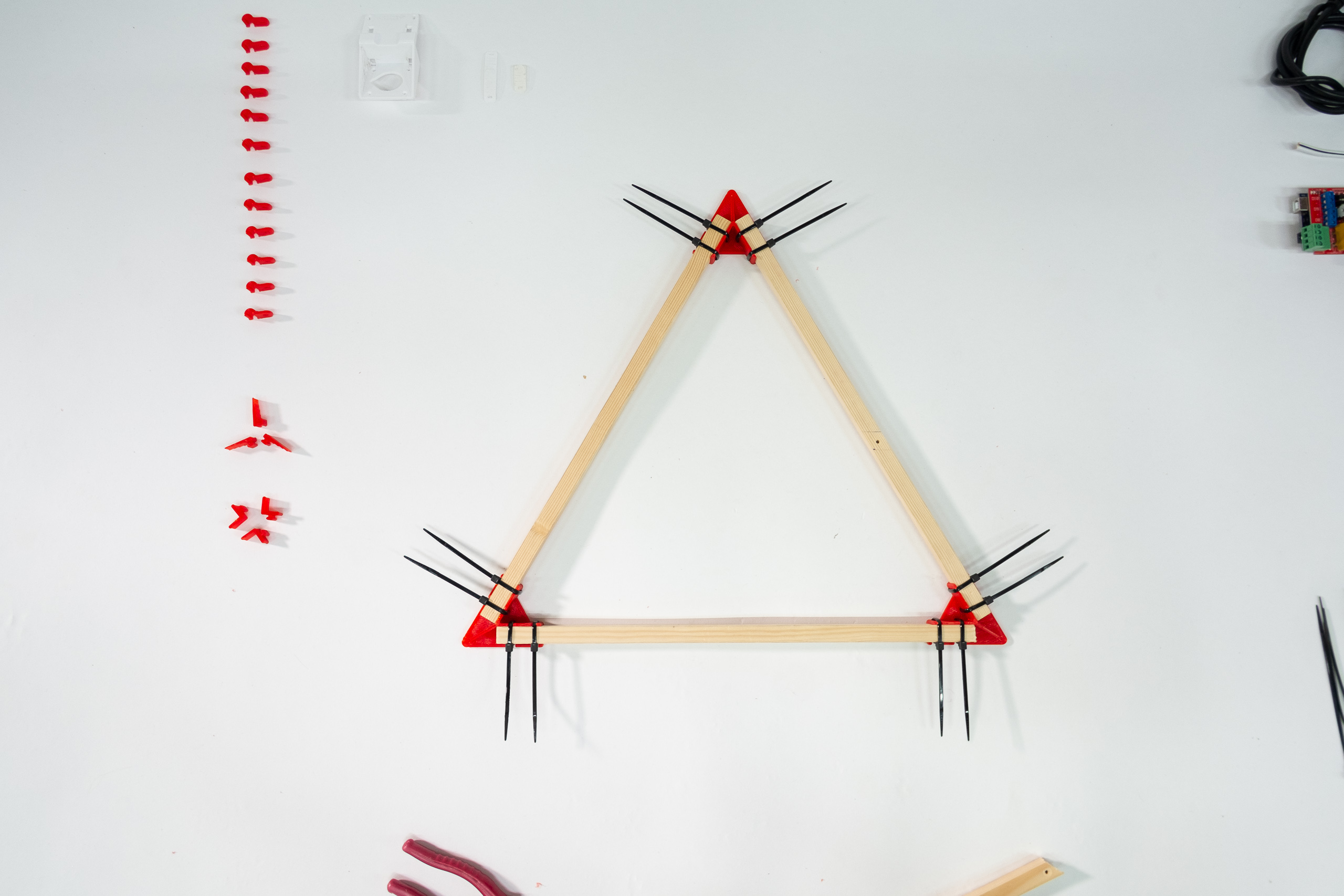
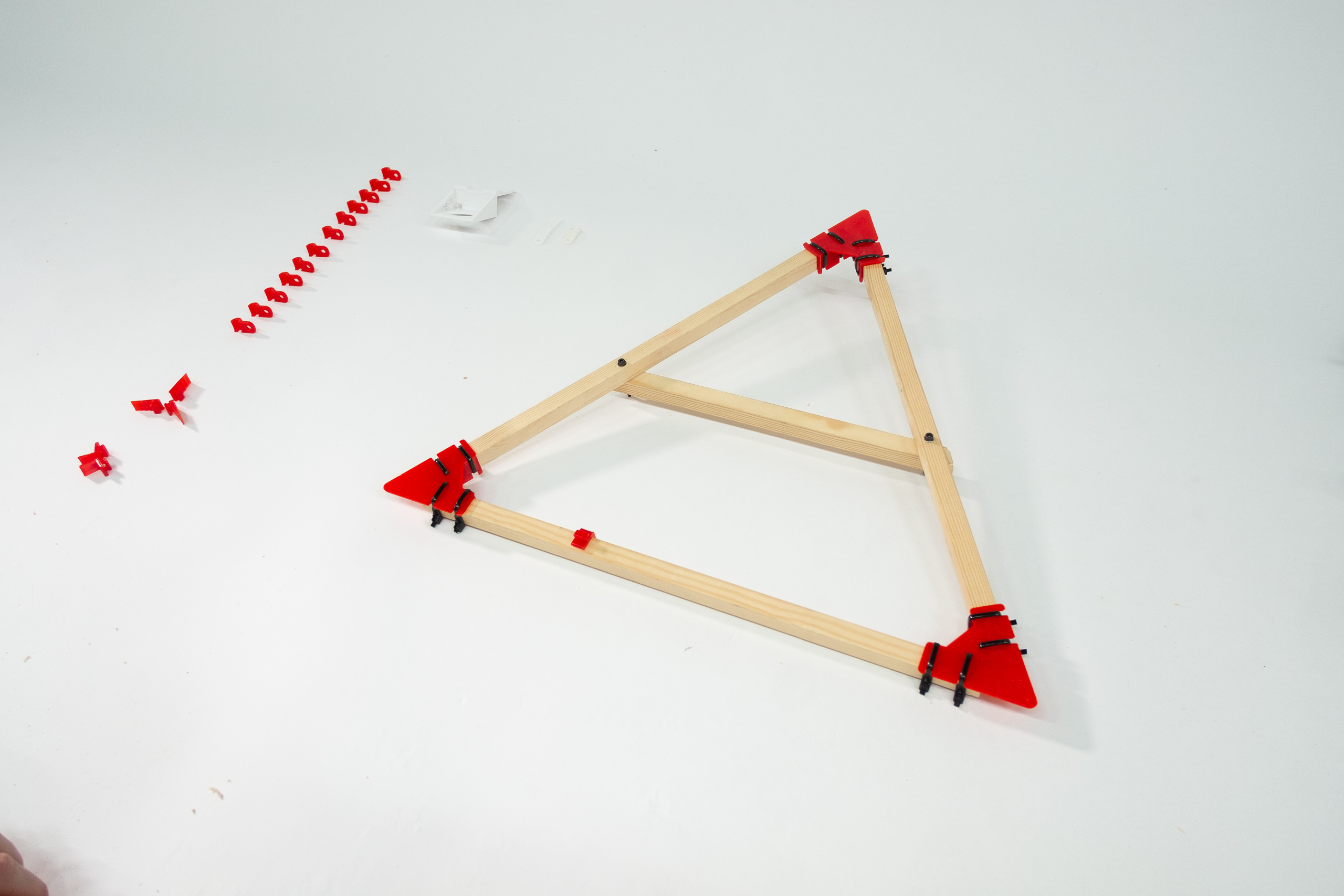
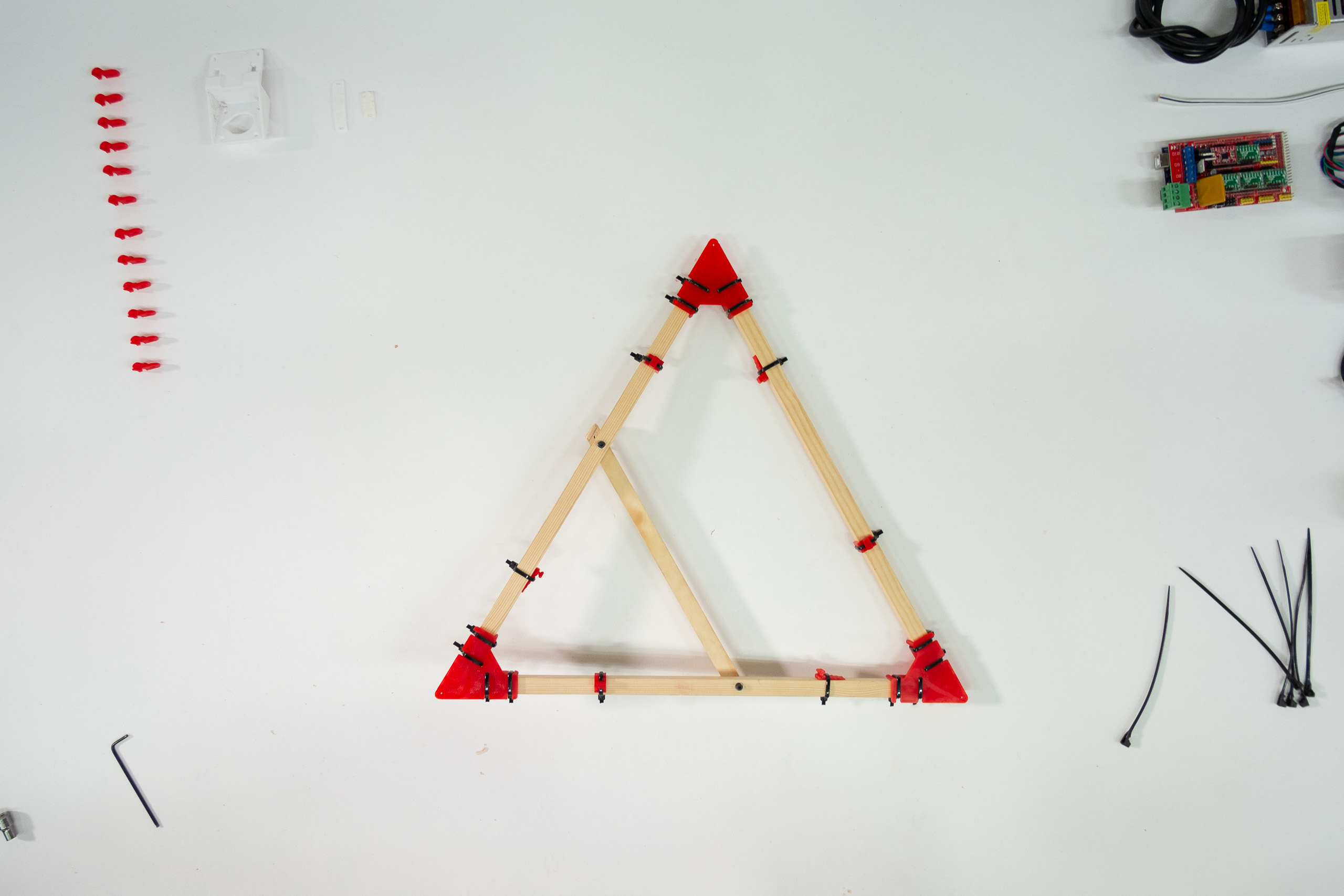
Grab your mover parts.
Your 40cm beam should be pushed right up to the root of the separator wall.
This is important in order to get the correct width of your mover triangle.
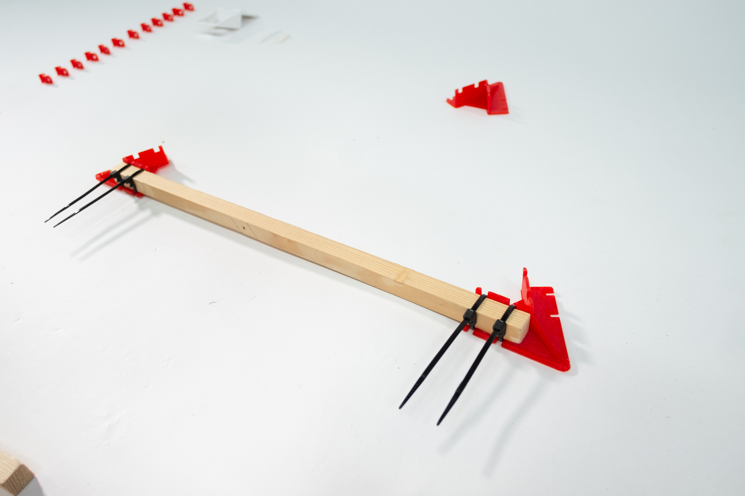
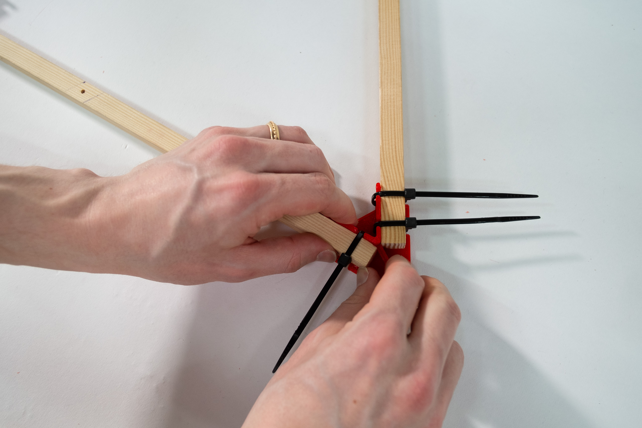
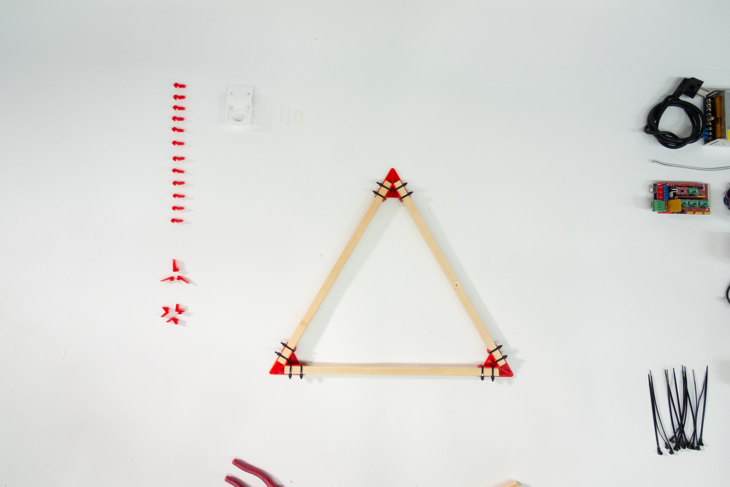
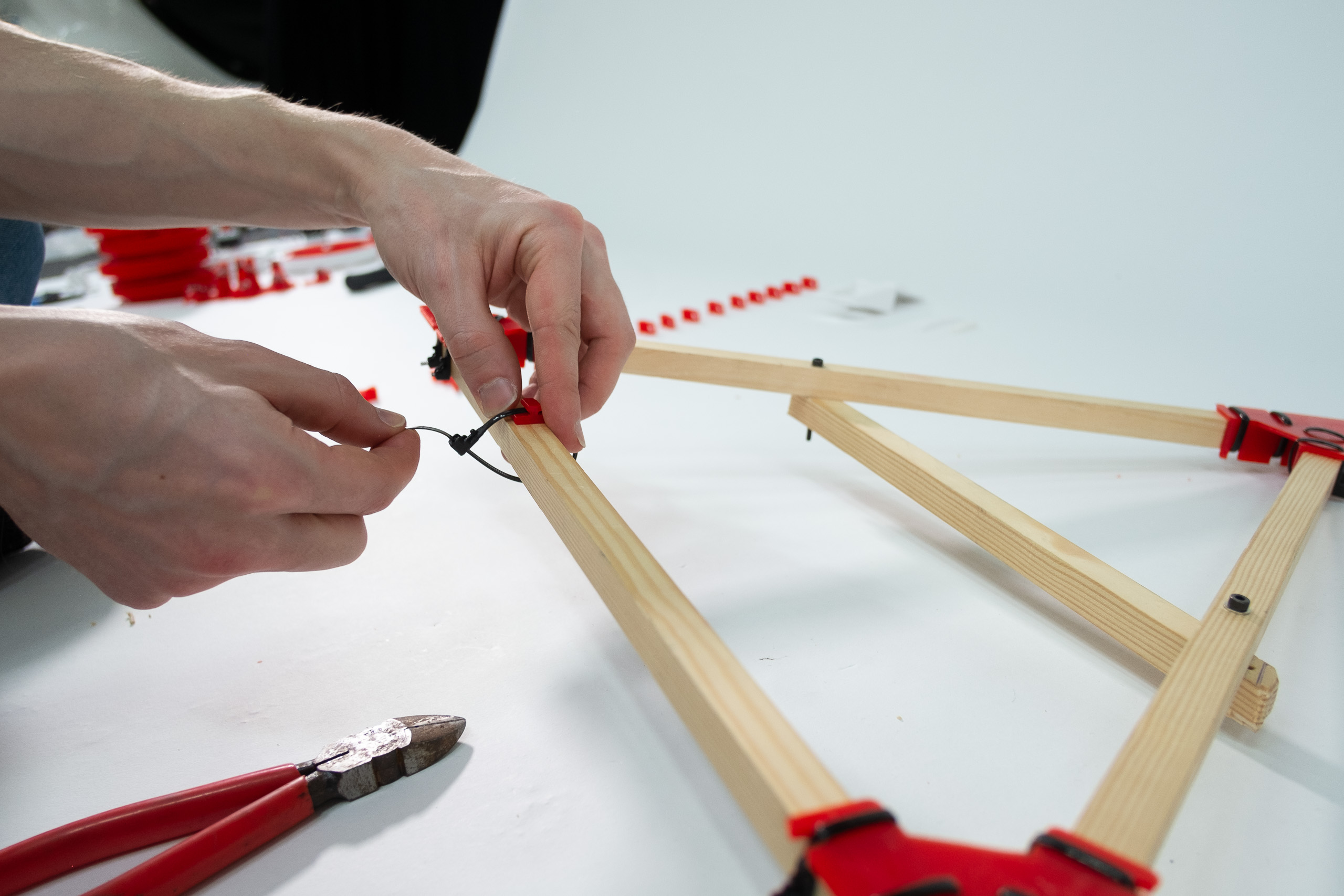
Attach with zipties loosely.
Ensure beams are flush with the root of the separator wall.
Then tighten as hard as you can without snapping the zipties.
The finished triangle should feel reasonably stiff.
It will not experience great forces during print, but it should not change dimensions easily.
Leave a few mm of ziptie, so you can after-tighten them later if needed.
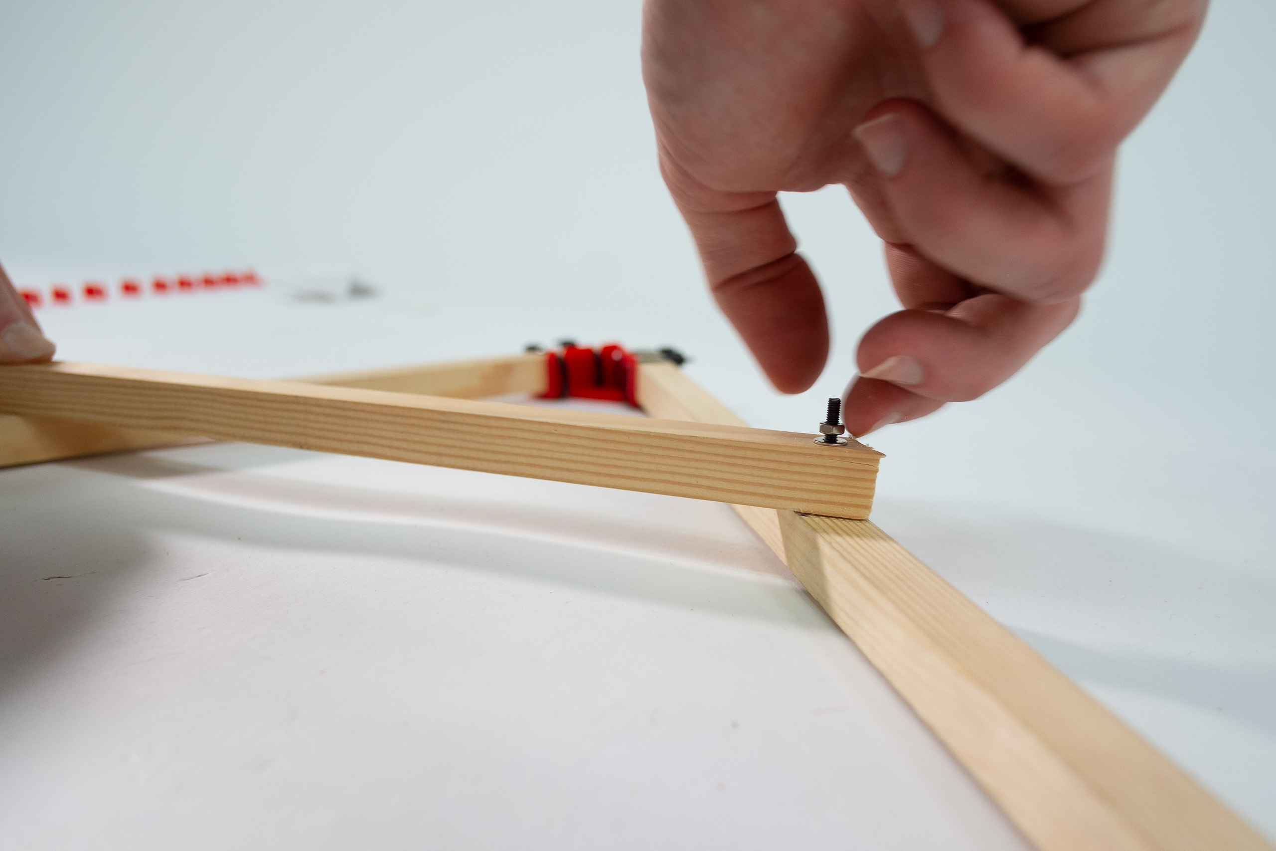
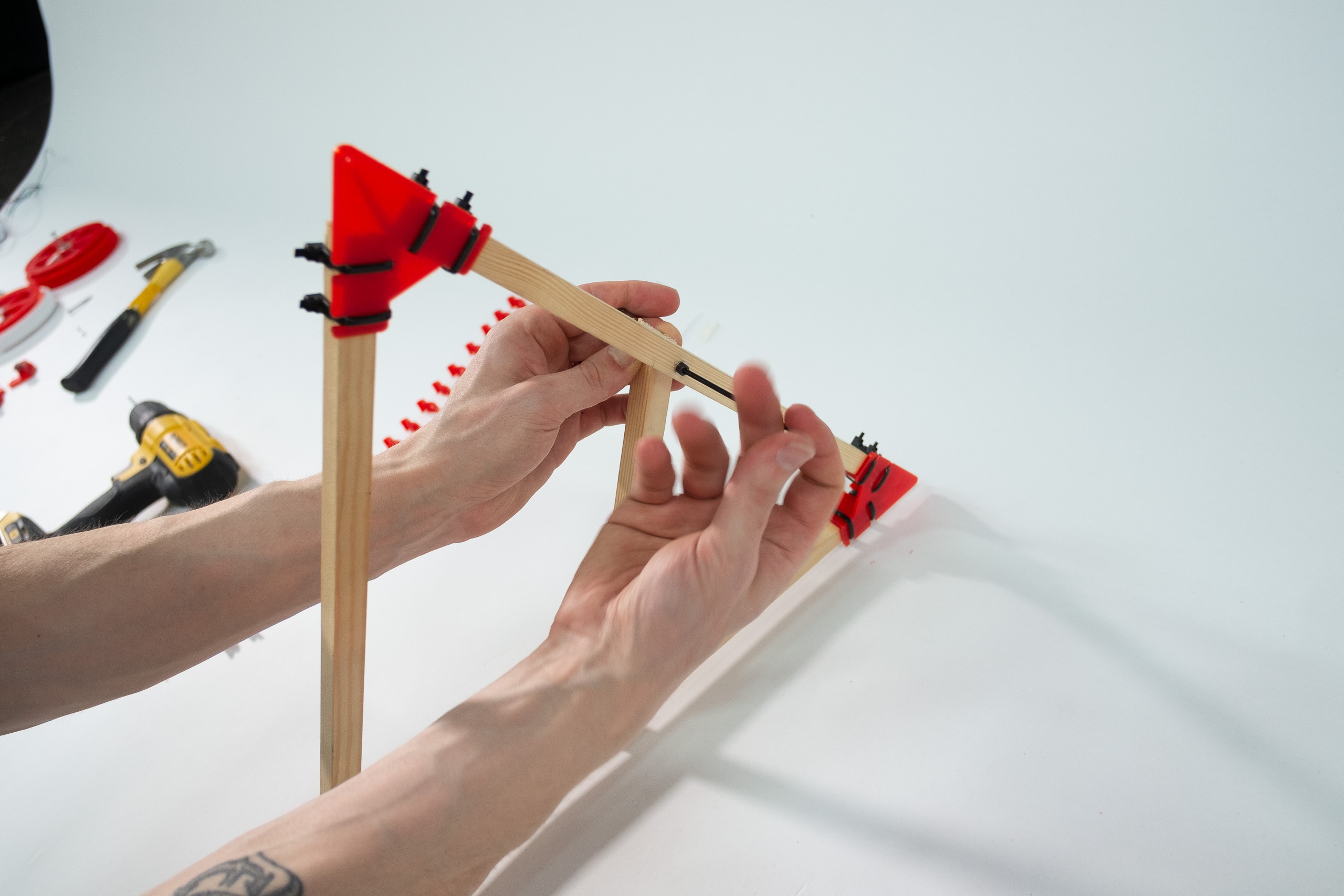
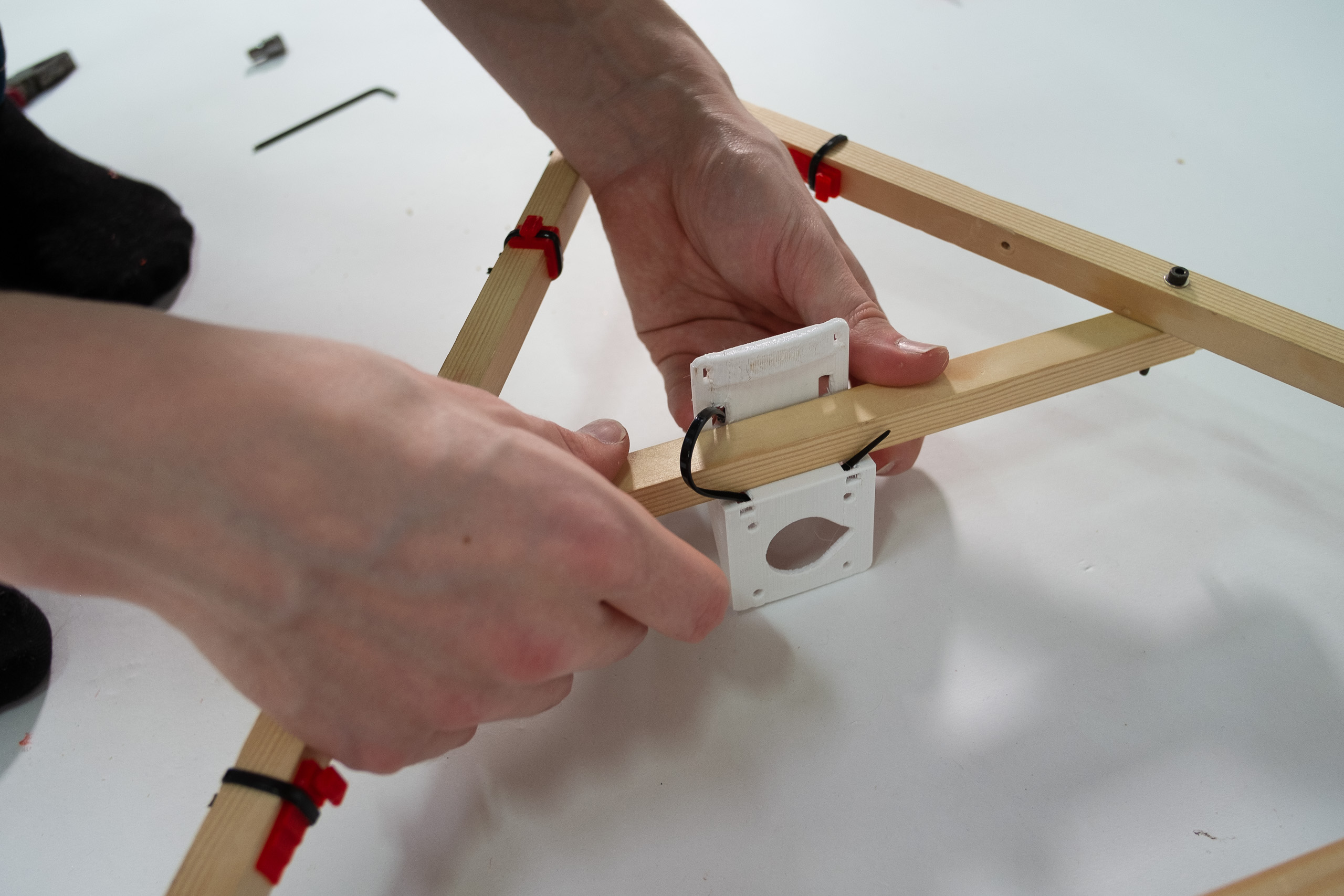
If you use wooden beams, you can drill a mounting hole right through your triangle side and your cross beam.
If you use carbon fibre beams, attach cross beam with zipties instead, like shown in this linked picture.
Use washers on both sides of the M3 screw.
Make the screw quite tight. If your wood is soft, the washer should slightly sink into the wood.
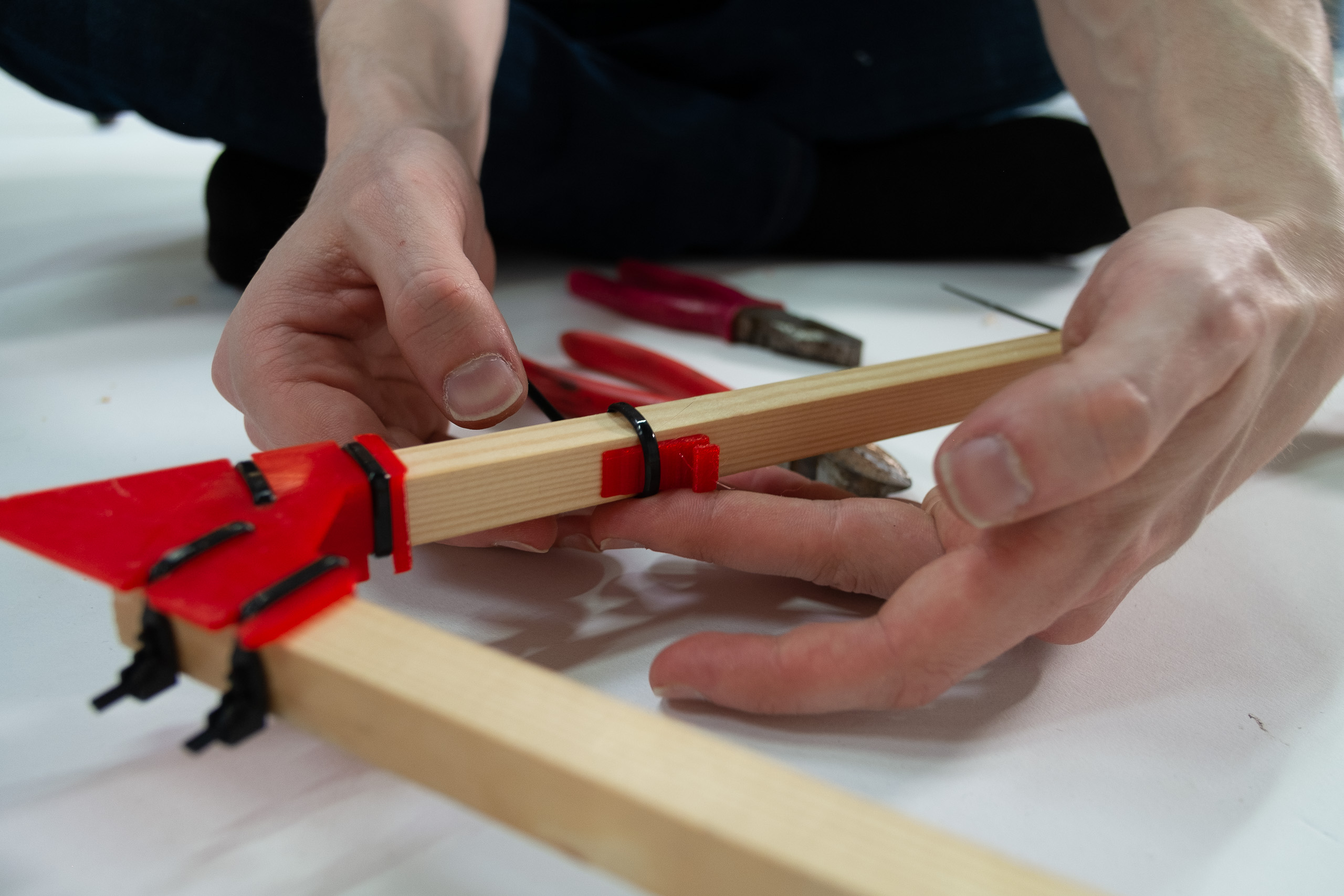
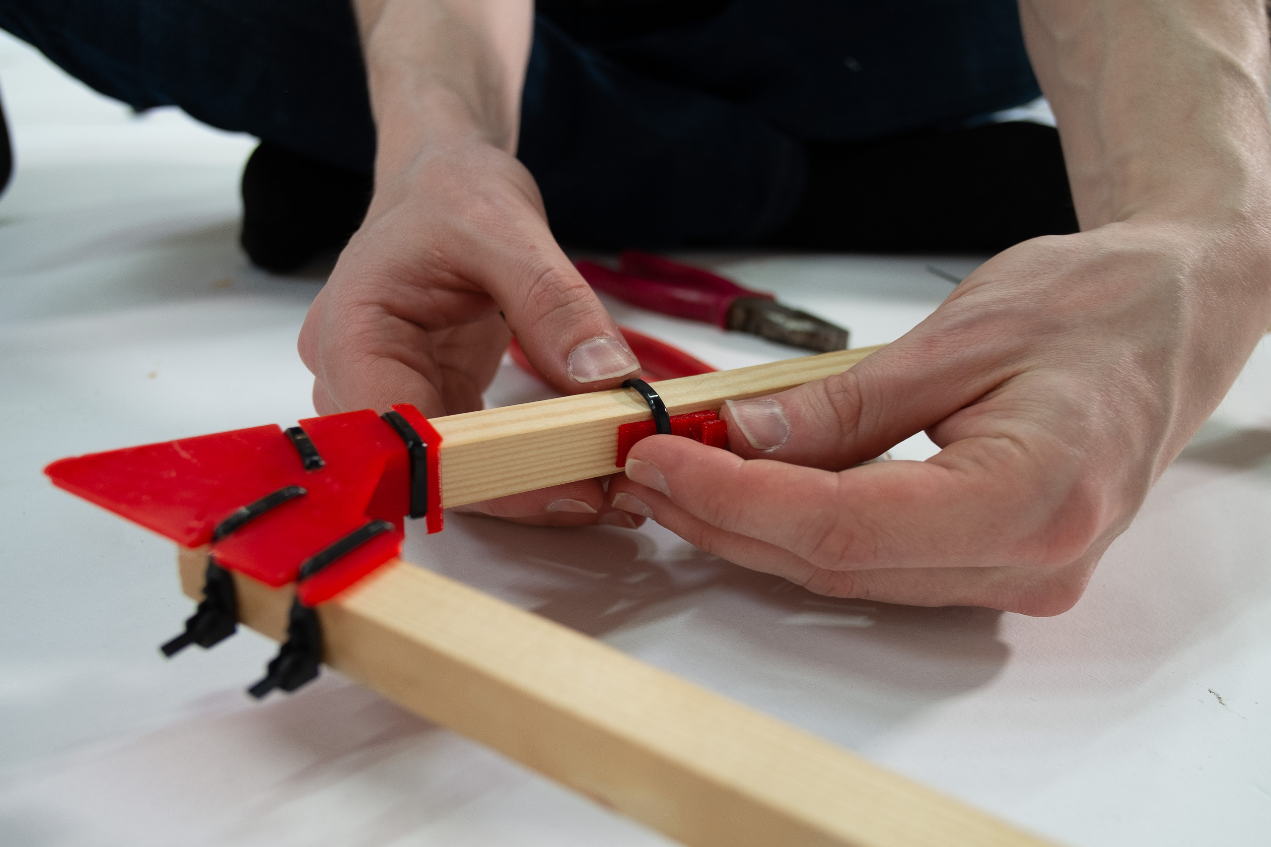
Now grab your beam sliders.
The ABC-beam sliders should be ziptied quite tightly.
The D-beam sliders should be ziptied loosely at first.
Tighten D-beam sliders by wedging them farther into the ziptie, pointing towards the closest corner.
Put ABC-sliders and D-sliders in opposite ends of each triangle side.
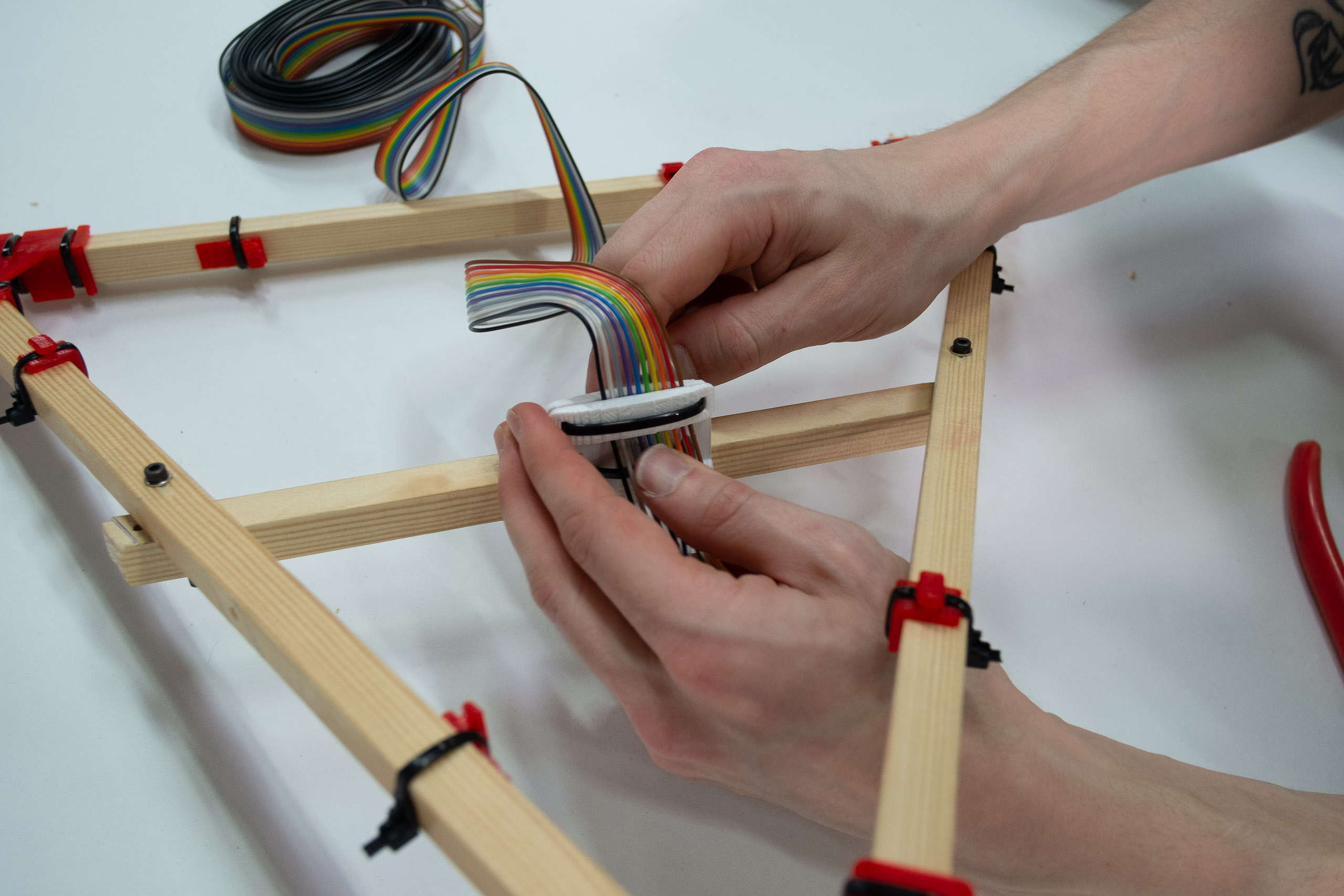
Route a ziptie over your crossbeam and through your extruder holder as shown.
Use two zipties like shown in the picture, or use one longer ziptie.
Tighten as hard as you can.
Add two more zipties, in straight loops around the beam.
Use the printed wedge to tighten the long ziptie(s).
Your extruder holder should now be very tightly attached to your cross beam.
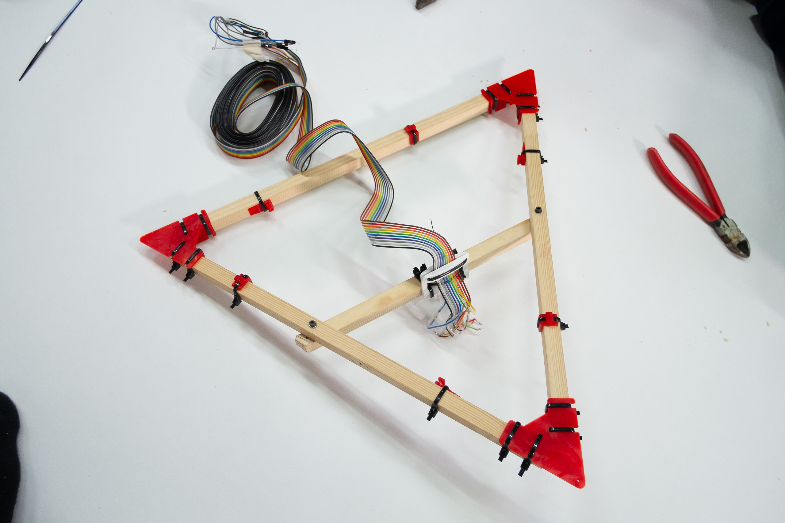
The ribbon cable is ziptied to the extruder holder for strain relief.
Mount your extruder+hot end of choice and put away the finished mover.
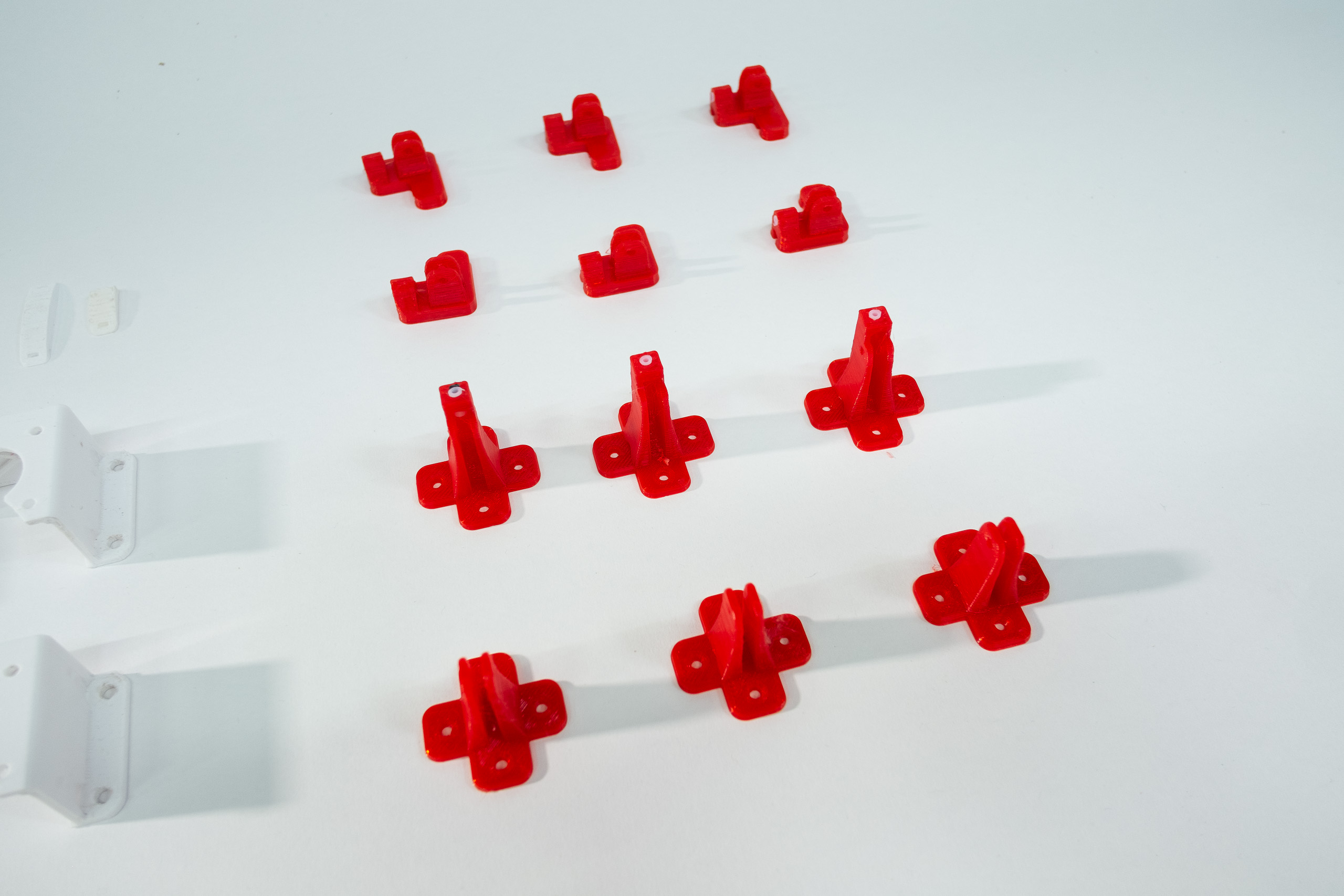
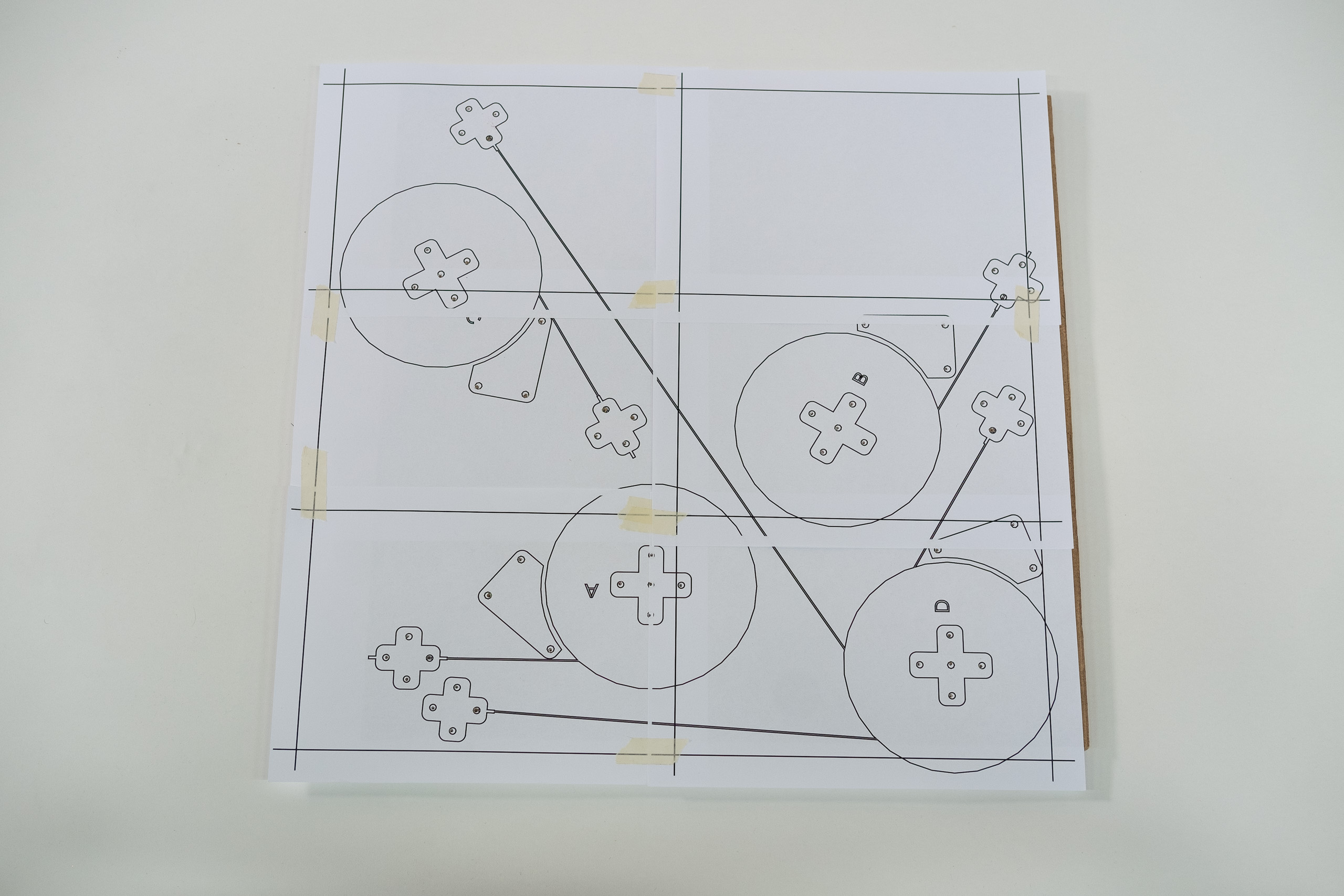
Grab your template 2d-prints.
Double-check that they are printed at 100% scale by comparing sizes of 2d-printed outlines with the bases of
your 3d-printed
parts.
Image of successful double-check.
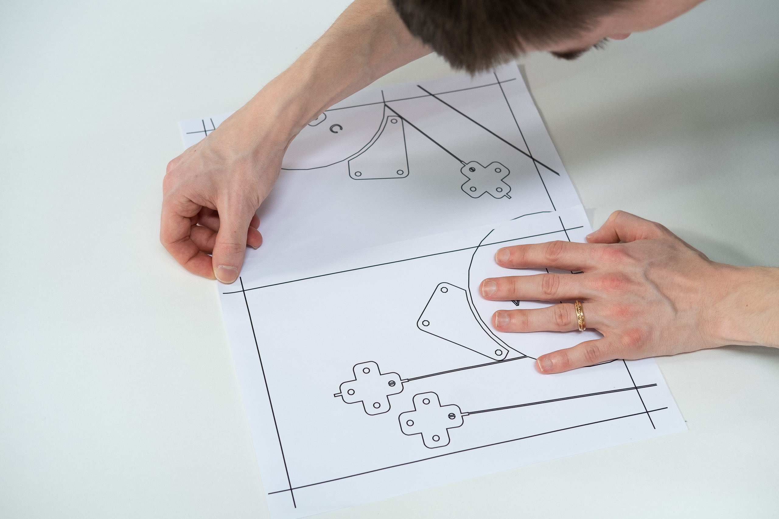
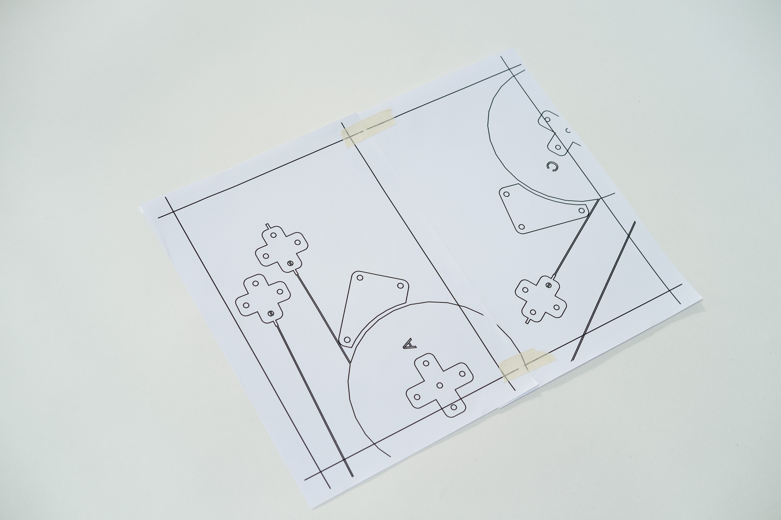
Place them so lines shine through. Ideally on a window or a glass table.
Align the overlaps perfectly on top of each other.
Tape together.
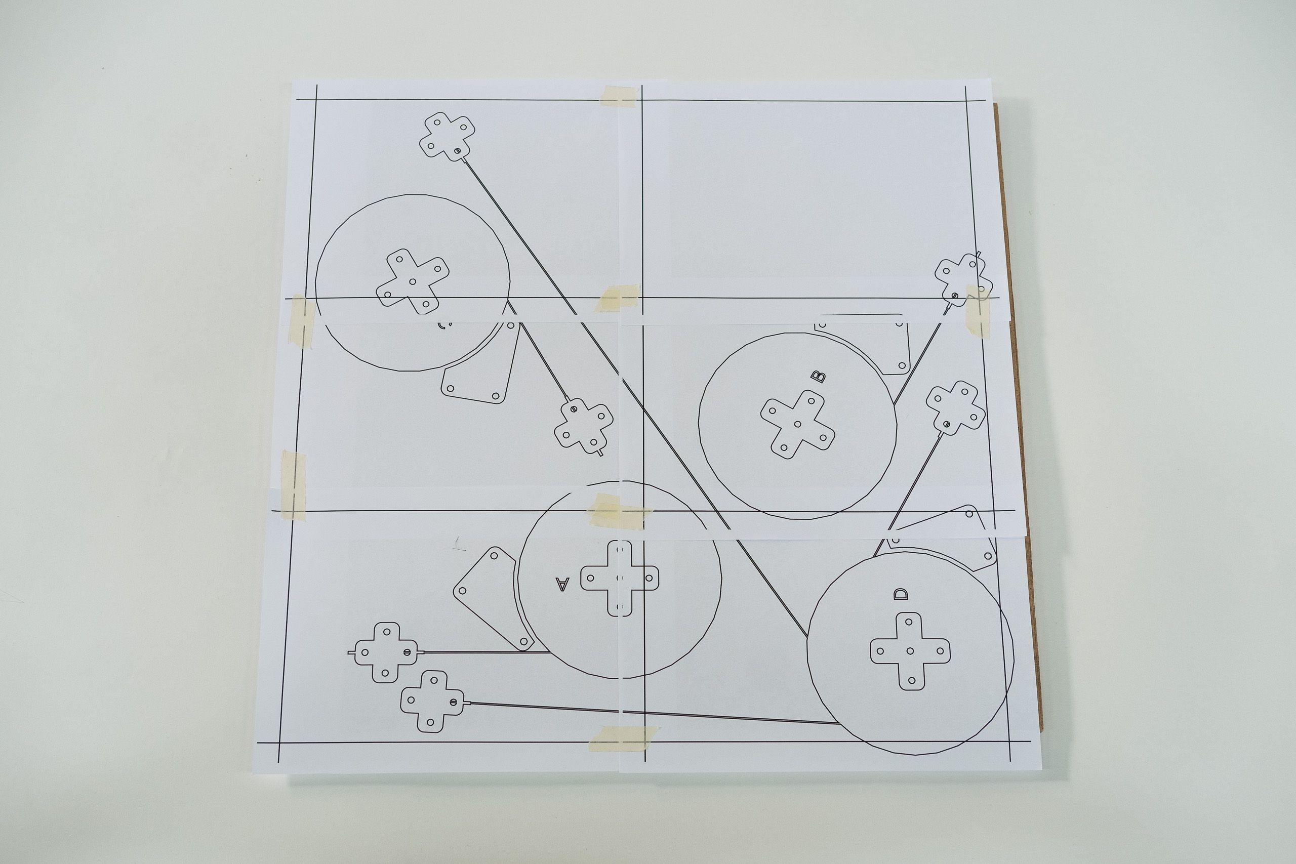
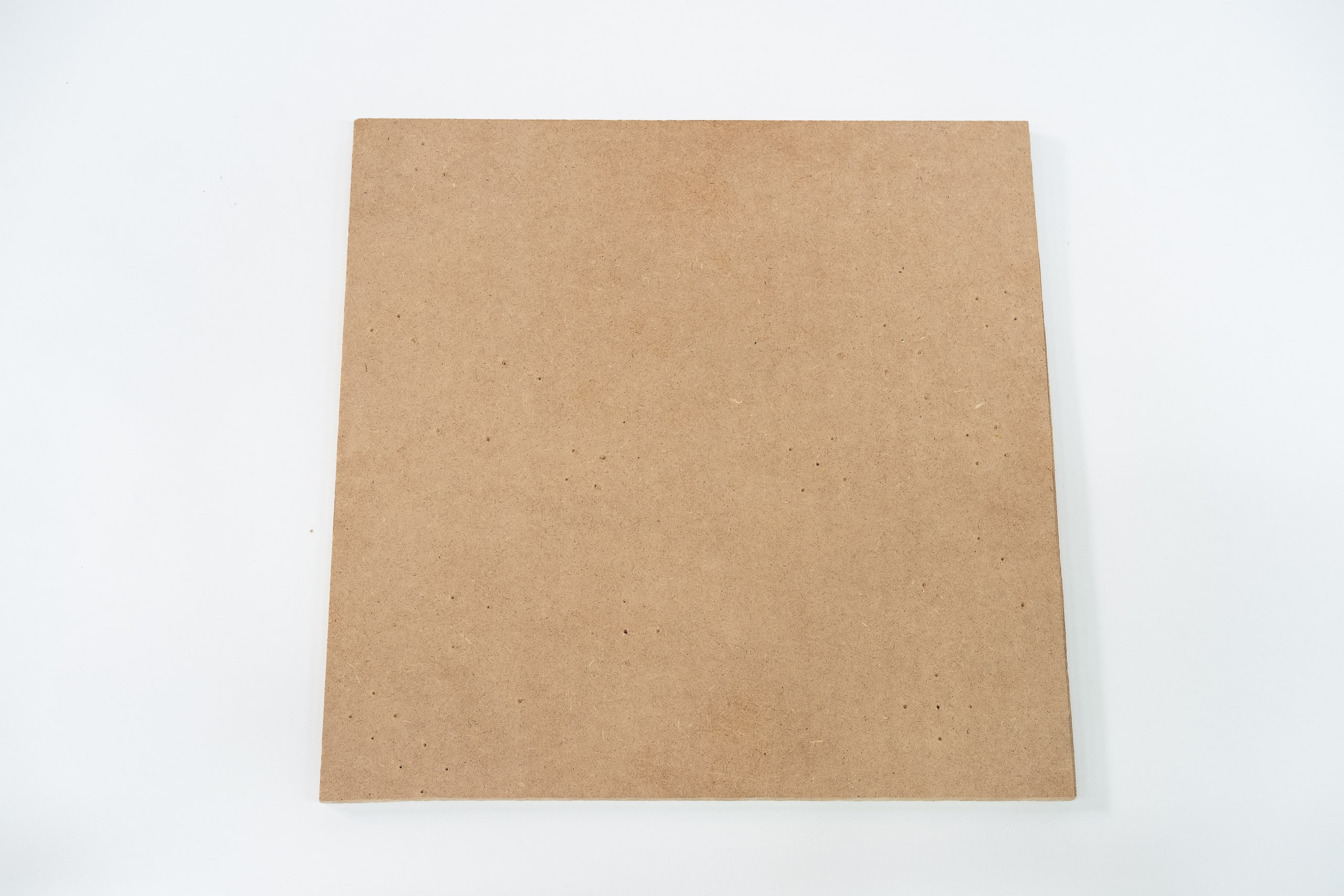
Place your finished 2d-template on your ceiling plate.
Screw the template flat onto the ceiling plate.
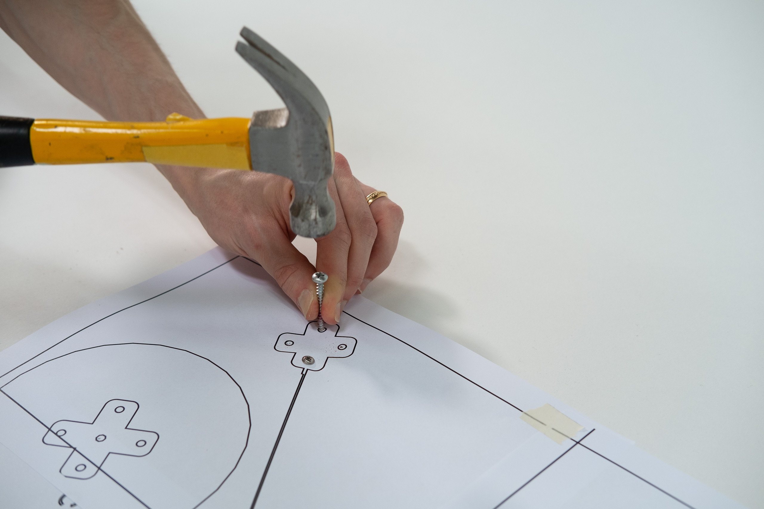
Hammer in markings through the centers of all the little circles.
The template with all the markings hammered looks like this.
The ceiling plate below should have visible marks like this.
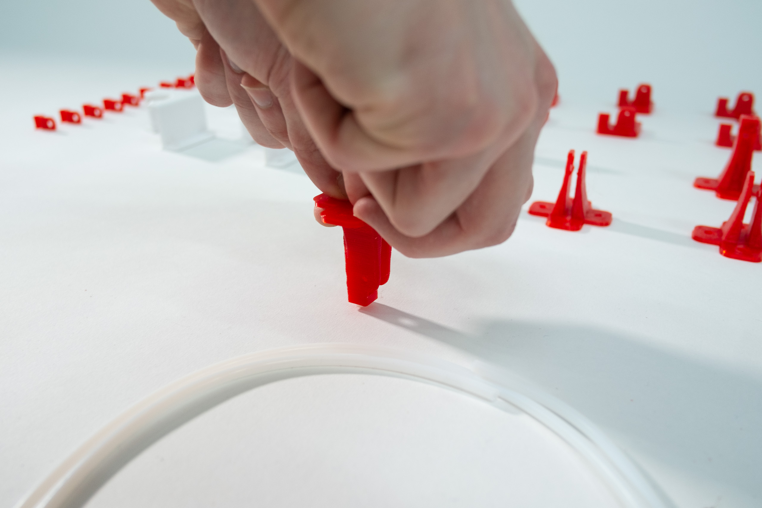
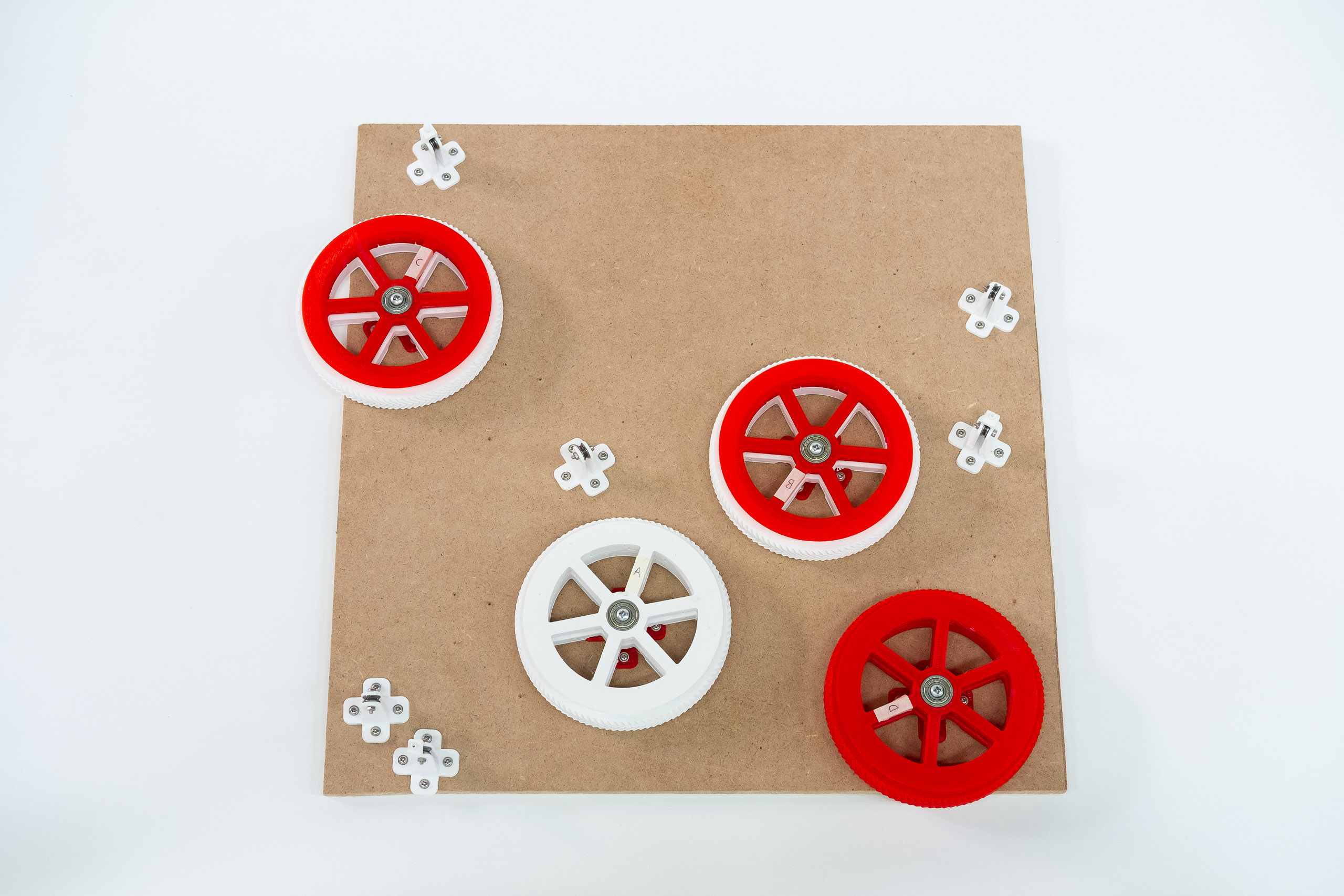
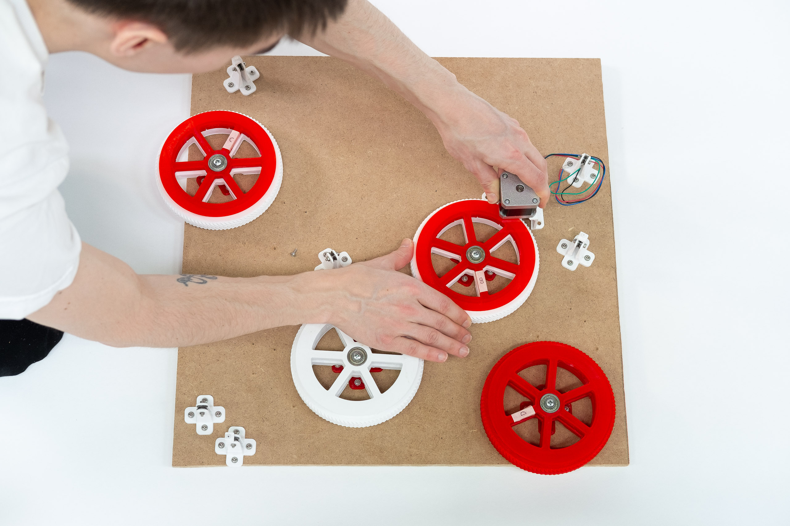
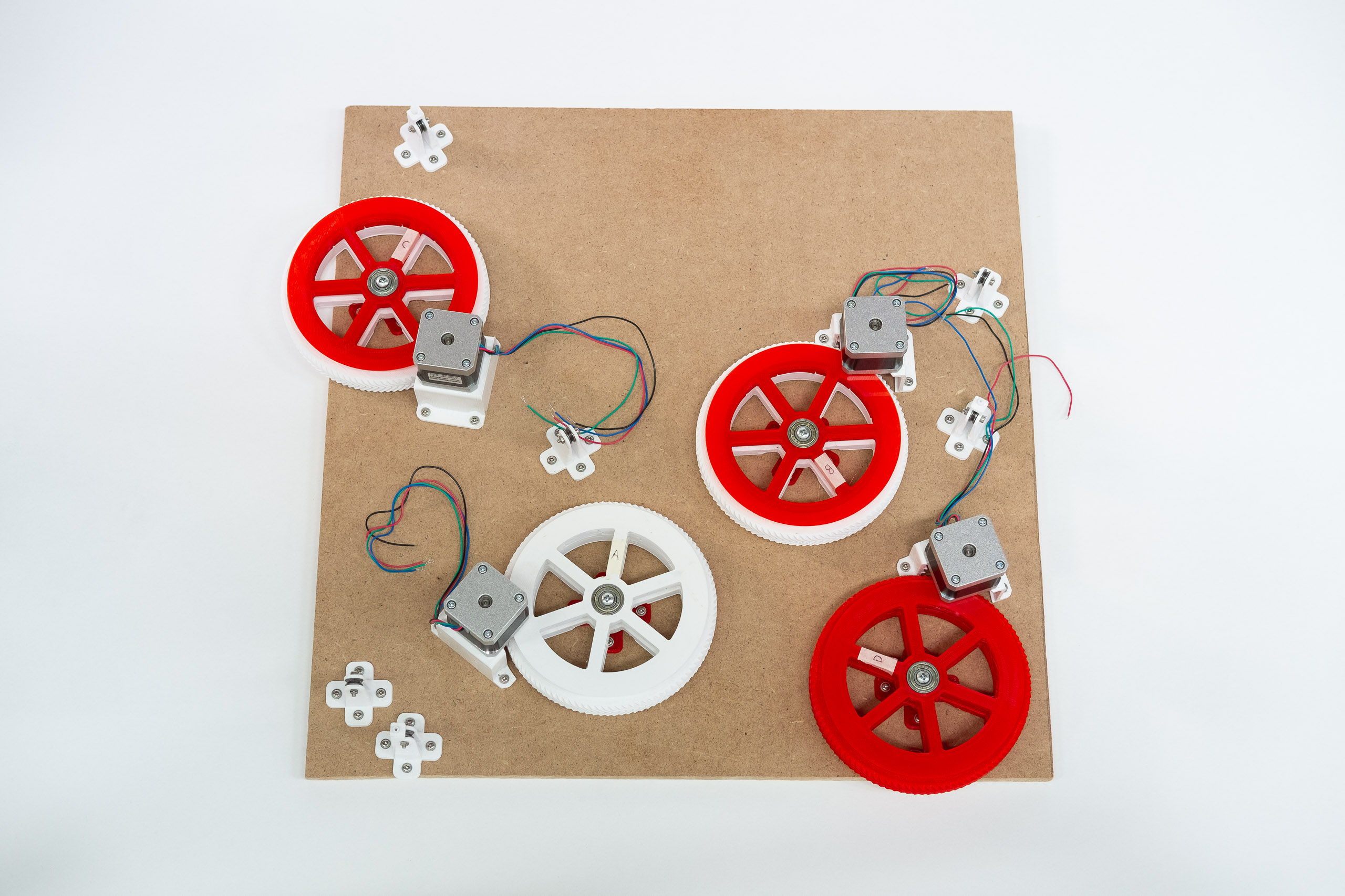
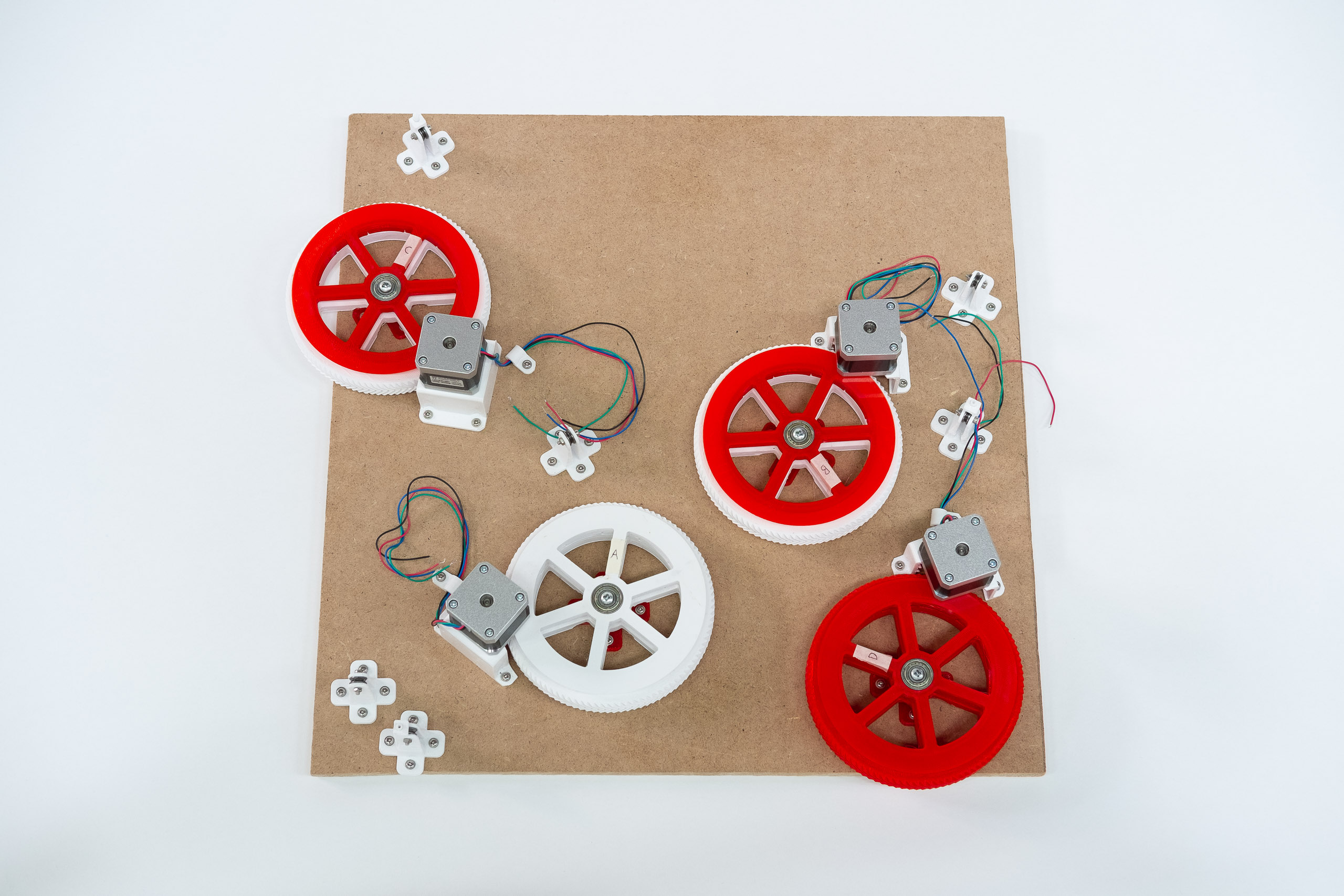
Now mount your prepared spools and linerollers.
Mind the orientation of the linerollers so line can enter like specified on the template.
Marking the spools with names A, B, C, and D, as specified on the template is useful.
Don't forget the long screws through the center of the spool cores.
A bit of play in the gears is harmless because the lines will pre-tension the gears anyways.
Gears that mesh badly or roll unevenly because of a too tight fit might cause problems later on.
Pointing motor wires away from their spool center is nice, but not critical.
Clamp down the motor wires as close to the motor bracket as you can.
Video of mounting parts to the ceiling plate.
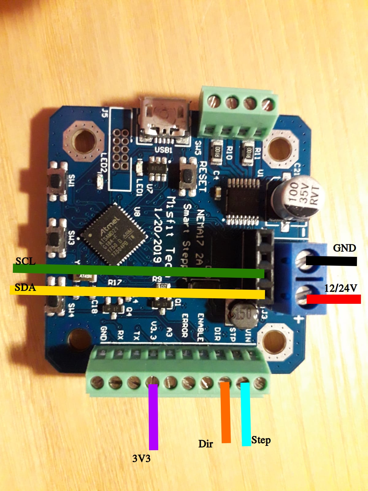
We don't have a complete wiring diagram with SmartSteppers, so please look at the following wiring diagram,
but note that the external 12V -> 5V level shifter is not needed, as this component is built into the
SmartSteppers.
... and wire in the SmartSteppers like this:
SmartStepper wiring.
Mounting
The only sources for Mounting instructions are videos:
If you're doing it manually (no SmartStepper), then look at this.
Also look at the video sources of Chris Riley and
Thomas
Sanladerer.
If you're using SmartStepper, then tobben has prepared a script that hopefully lets you avoid having to measure
anchor positions manually: here. It is a bit hard to use,
be sure to read te README, and to file an issue if you find a bug or improvement.
You can also submit merge requests and issues towards this documentation directly,
here.
Building, mounting, calibrating, and running a HP3 is hard.
You are not alone.
Be sure to check out the resources, there are some quite good ones.
- tobben 👷
The raw text source of this manual is published under the GPL-2.0
license, and is being maintained in the hangprinter-org repo. All images and videos are also published under the GPL-2.0, except the
wiring diagram, which is published under the GPLv3
license.